
Firmware Manual


9000X AF Drives
5-10 For more information visit: www.eaton.com
MN04004001E
August 2010
PID Control Application
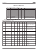
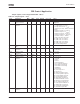
Table 5-5: Output Signals — G1.3 (Continued)
Code Parameter Min. Max. Unit Default Cust ID Note
P1.3.9 Relay output 2
function
0 23 3 314 Same as parameter 1.3.7
P1.3.10 Output frequency
limit 1 supervision
0 2 0 315 0 = No limit
1 = Low limit supervision
2 = High limit supervision
P1.3.11 Output frequency
limit 1;
Supervised value
0.00 Par. 1.1.2 Hz 0.00 316
P1.3.12 Output frequency
limit 2 supervision
0 2 0 346 0 = No limit
1 = Low limit supervision
2 = High limit supervision
P1.3.13 Output frequency
limit 2;
Supervised value
0.00 Par. 1.1.2 Hz 0.00 347
P1.3.14 Torque limit
supervision
0 2 0 348 0 = Not used
1 = Low limit supervision
2 = High limit supervision
P1.3.15 Torque limit
supervision value
0.0 300.0 % 100.0 349
P1.3.16 Reference limit
supervision
0 2 0 350 0 = Not used
1 = Low limit
2 = High limit
P1.3.17 Reference limit
supervision value
0.00 Par. 1.1.2 Hz 0.00 351
P1.3.18 External
brake-off delay
0.0 100.0 s 0.5 352
P1.3.19 External
brake-on delay
0.0 100.0 s 1.5 353
P1.3.20 FC temperature
supervision
0 2 0 354 0 = Not used
1 = Low limit
2 = High limit
P1.3.21 FC temperature
supervised value
-10 75 °C 40 355
P1.3.22
Analog output 2
signal selection
0 0.1 471 TTF programming method used.
See Page 6-3.
P1.3.23 Analog output 2
function
0 13 4 472 Same as parameter 1.3.2
P1.3.24 Analog output 2
filter time
0.00 10.00 s 1.00 473 0 = No filtering
P1.3.25 Analog output 2
inversion
0 1 0 474 0 = Not inverted
1 = Inverted
P1.3.26 Analog output 2
minimum
0 1 0 475 0 = 0 mA
1 = 4 mA
P1.3.27 Analog output 2
scaling
10 1000 % 100 476