
Firmware Manual


9000X AF Drives
MN04004001E
For more information visit: www.eaton.com
4-7
August 2010
Multi-Step Speed Control Application
Output Signals (Control Keypad: Menu M1
➔
G1.3)
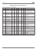
Table 4-5: Output Signals — G1.3
Code Parameter Min. Max. Unit Default Cust ID Note
P1.3.1
AO1 signal selection 0 A.1 464 TTF programming method used.
See Page 6-3.
P1.3.2 Analog output function 0 8 1 307 0 = Not used
1 = Output freq. (0 – f
max
)
2 = Freq. reference (0 – f
max
)
3 = Motor speed (0 – Motor
nominal speed)
4 = Motor current (0 – I
nMotor
)
5 = Motor torque (0 – T
nMotor
)
6 = Motor power (0 – P
nMotor
)
7 = Motor voltage (0 – U
nMotor
)
8 = DC-bus volt (0 – 1000V)
P1.3.3 Analog output filter
time
0.00 10.00 s 1.00 308 0 = No filtering
P1.3.4 Analog output
inversion
0 1 0 309 0 = Not inverted
1 = Inverted
P1.3.5 Analog output
minimum
0 1 0 310 0 = 0 mA
1 = 4 mA
P1.3.6 Analog output scale 10 1000 % 100 311
P1.3.7 Digital output 1
function
0 22 1 312 0 = Not used
1 = Ready
2 = Run
3 = Fault
4 = Fault inverted
5 = FC overheat warning
6 = Ext. fault or warning
7 = Ref. fault or warning
8 = Warning
9 = Reversed
10 = Jogging spd selected
11 = At speed
12 = Mot. regulator active
13 = OP freq.limit superv. 1
14 = OP freq.limit superv. 2
15 = Torque limit superv.
16 = Ref. limit superv.
17 = Ext. brake control
18 = Remote Control Active
19 = FC temp. limit superv.
20 = Unrequested rotation
direction
21 = Ext. brake control inverted
22 = Thermistor fault/warn.
P1.3.8 Relay output 1 function 0 22 2 313 Same as parameter 1.3.7
P1.3.9 Relay output 2 function 0 22 3 314 Same as parameter 1.3.7
P1.3.10 Output frequency limit
1 supervision
0 2 0 315 0 = No limit
1 = Low limit supervision
2 = High limit supervision