
Firmware Manual


9000X AF Drives
4-6 For more information visit: www.eaton.com
MN04004001E
August 2010
Multi-Step Speed Control Application
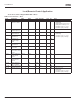
Table 4-4: Input Signals — G1.2 (Continued)
Remember to place jumpers of block X2 accordingly. See 9000X AF Drives User Manual, Chapter 4.
Code Parameter Min. Max. Unit Default Cust ID Note
P1.2.5 AI1 custom setting
minimum
0.00 100.00 % 0.00 321 Analog input 1 scale minimum
P1.2.6 AI1 custom setting
maximum
0.00 100.00 % 100.0 322 Analog input 1 scale maximum
P1.2.7 AI1 signal
inversion
0 1 0 323 Analog input 1 reference
inversion yes/no
P1.2.8 AI1 signal filter
time
0.00 10.00 s 0.10 324 Analog input 1 reference filter
time. constant
P1.2.9
AI2 signal
selection
0 A.2 388 TTF programming method used.
See Page 6-3.
P1.2.10 AI2 signal range 0 2 1 325 0 = 0 – 20 mA
1 = 4 – 20 mA
2 = custom setting range
P1.2.11 AI2 custom setting
minimum
0.00 100.00 % 0.00 326 Analog input 2 scale minimum
P1.2.12 AI2 custom setting
maximum
0.00 100.00 % 100.00 327 Analog input 2 scale maximum
P1.2.13 AI2 signal
inversion
0 1 0 328 Analog input 2 reference
inversion yes/no
P1.2.14 AI2 signal filter
time
0.00 10.00 s 0.10 329 Analog input 2 reference filter
time, constant
P1.2.15 Reference scaling
minimum value
0.00 Par. 1.2.16 Hz 0.00 303 Selects the frequency that
corresponds to the min.
reference signal
P1.2.16 Reference scaling
maximum value
0.00 320.00 Hz 0.00 304 Selects the frequency that
corresponds to the max.
reference signal
0.00 = No scaling
>0 = scaled max. value
P1.2.17 Free analog input
signal selection
0 2 0 361 0 = Not used
1 = U
in
(analog volt. input)
2 = I
in
(analog curr. input)
P1.2.18 Free analog input
function
0 4 0 362 0 = No function
1 = Reduces current limit (par.
1.1.5)
2 = Reduces DC braking current
3 = Reduces accel. and decel.
times
4 = Reduces torque supervision
limit