
Firmware Manual


9000X AF Drives
2-6 For more information visit: www.eaton.com
MN04004001E
August 2010
Standard Application
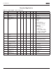
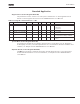
Table 2-5: Output Signals — G1.3 (Continued)
Code Parameter Min. Max. Unit Default Cust ID Note
P1.3.4 Analog output
inversion
0 1 0 309 0 = Not inverted
1 = Inverted
P1.3.5 Analog output
minimum
0 1 0 310 0 = 0 mA
1 = 4 mA
P1.3.6 Analog output scale 10 1000 % 100 311
P1.3.7 Digital output 1
function
0 16 1 312 0 = Not used
1 = Ready
2 = Run
3 = Fault
4 = Fault inverted
5 = FC overheat warning
6 = Ext. fault or warning
7 = Ref. fault or warning
8 = Warning
9 = Reversed
10 = Preset speed 1
11 = At speed
12 = Mot. regulator active
13 = OP freq. limit 1 superv.
14 = Remote Control Active
15 = Thermistor fault/warng
16 = Fieldbus input data
P1.3.8 Relay output 1
function
0 16 2 313 Same as parameter 1.3.7
P1.3.9 Relay output 2
function
0 16 3 314 Same as parameter 1.3.7
P1.3.10 Output frequency limit
1 supervision
0 2 0 315 0 = No limit
1 = Low limit supervision
2 = High limit supervision
P1.3.11 Output frequency limit
1; Supervised value
0.00 320.00 Hz 0.00 316
P1.3.12
Analog output 2 signal
selection
0 0.1 471 TTF programming method used.
See Page 6-3.
P1.3.13 Analog output 2
function
0 8 4 472 Same as parameter 1.3.2
P1.3.14 Analog output 2 filter
time
0.00 10.00 s 1.00 473 0 = No filtering
P1.3.15 Analog output 2
inversion
0 1 0 474 0 = Not inverted
1 = Inverted
P1.3.16 Analog output 2
minimum
0 1 0 475 0 = 0 mA
1 = 4 mA
P1.3.17 Analog output 2
scaling
10 1000 % 100 476