
Firmware Manual


9000X AF Drives
MN04004001E
For more information visit: www.eaton.com
2-5
August 2010
Standard Application
Input Signals (Control Keypad: Menu M1
➔
G1.2)
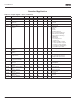
Table 2-4: Input Signals — G1.2
Rising edge required to start.
CP = control place.
Output Signals (Control Keypad: Menu M1
➔
G1.3)
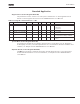
Table 2-5: Output Signals — G1.3
Code Parameter Min. Max. Unit Default Cust ID Note
P1.2.1
Start/Stop logic 0 6 0 300 DIN1 DIN2
0
1
2
3
4
5
6
Start fwd
Start/Stop
Start/Stop
Start pulse
Fwd
Start
/Stop
Start
/Stop
Start rvs
Rvs/Fwd
Run enable
Stop pulse
Rvs
Rvs/Fwd
Run enable
P1.2.2
DIN3 function 0 7 1 301 0 = Not used
1 = Ext. fault. closing cont.
2 = Ext. fault. opening cont.
3 = Run enable
4 = Acc./Dec. time select.
5 = Force CP to Remote
6 = Rvs (if par. 1.2.1 = 3)
P1.2.3 Current reference
offset
0 1 1 302 0 = 0 – 20mA
1 = 4 – 20mA
P1.2.4 Reference scaling
minimum value
0.00 Par. 1.2.5 Hz 0.00 303 Selects the frequency that
corresponds to the min.
reference signal
0.00 = No scaling
P1.2.5 Reference scaling
maximum value
0.00 320.00 Hz 0.00 304 Selects the frequency that
corresponds to the max.
reference signal
0.00 = No scaling
P1.2.6 Reference inversion 0 1 0 305 0 = Not inverted
1 = Inverted
P1.2.7 Reference filter time 0.00 10.00 s 0.10 306 0 = No filtering
P1.2.8
AI1 signal selection A.1 377 TTF programming method used.
See Page 6-3.
P1.2.9
AI2 signal selection A.2 388 TTF programming method used.
See Page 6-3.
Code Parameter Min. Max. Unit Default Cust ID Note
P1.3.1
Analog output 1 signal
selection
0 A.1 464 TTF programming method used.
See Page 6-3.
P1.3.2 Analog output
function
0 8 1 307 0 = Not used
1 = Output freq. (0 – f
max
)
2 = Freq. reference (0 – f
max
)
3 = Motor speed (0 – Motor
nominal speed)
4 = Motor current (0 – I
nMotor
)
5 = Motor torque (0 – T
nMotor
)
6 = Motor power (0 – P
nMotor
)
7 = Motor voltage (0 – U
nMotor
)
8 = DC-Bus volt (0 – 1000V)
P1.3.3 Analog output filter
time
0.00 10.00 s 1.00 308 0 = No filtering