
Firmware Manual


9000X AF Drives
MN04004001E
For more information visit: www.eaton.com
A-5
August 2010
Appendix A
Parameters of Underload Protection
ID713 to ID716
General
The purpose of the motor underload protection is to ensure that there is load on the motor
when the drive is running. If the motor loses its load there might be a problem in the process,
e.g. a broken belt or a dry pump.
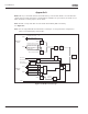
Motor underload protection can be adjusted by setting the underload curve with parameters
ID714 (Field weakening area load) and ID715 (Zero frequency load), see below. The underload
curve is a squared curve set between the zero frequency and the field weakening point. The
protection is not active below 5 Hz (the underload time counter is stopped).
The torque values for setting the underload curve are set in percentage which refers to the
nominal torque of the motor. The motor’s name plate data. parameter motor nominal current
and the drive’s nominal current I
H
are used to find the scaling ratio for the internal torque
value. If other than nominal motor is used with the drive, the accuracy of the torque
calculation decreases.
Fieldbus Control Parameters
ID850 to ID859
The Fieldbus control parameters are used when the frequency or the speed reference comes
from the fieldbus (Modbus, Profibus, DeviceNet, etc.). With the Fieldbus Data Out Selection
1 – 8, you can monitor values from the fieldbus.