
Firmware Manual


9000X AF Drives
MN04004001E
For more information visit: www.eaton.com
8-79
August 2010
Description of Parameters
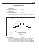
Figure 8-57: Example of Adjustable Frequency Drive and
Two Auxiliary Drives with Bypassed PID Controller
1020 PID controller bypass 7 (P1.9.16)
With this parameter, the PID controller can be programmed to be bypassed. Then the
frequency of the controlled drive and the starting points of the auxiliary drives are
defined according to the actual value signal. See Figure 8-57.
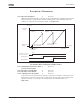
1021 Analog input selection for input
pressure measurement
7 (P1.9.17)
1022 Input pressure high limit 7 (P1.9.18)
1023 Input pressure low limit 7 (P1.9.19)
1024 Output pressure drop value 7 (P1.9.20)
In pressure increase stations there may be need for decreasing the output pressure if
the input pressure decreases below a certain limit. The input pressure measurement
which is needed is connected to the analog input selected with ID1021. See
Figure 8-58.
Output Freq.
Max. Freq.
(ID102)
Start Freq. of the Aux. Drive 1
(ID1002)
Start Freq. of the Aux. Drive 2
(ID1004)
Minimum Freq.
(ID101)
Stop Freq. of the Aux.
Drive 1 (ID1003)
Stop Freq. of the Aux.
Drive 2 (ID1005)
Actual Value
Maximum of the
Actual ValueMinimum of the
Actual Value
Start/Stop Control of
the Freq. Converter
Stop
Start
Stop
Start
Stop
Start
Auxiliary Drive 1
Auxiliary Drive 2