
Firmware Manual


9000X AF Drives
MN04004001E
For more information visit: www.eaton.com
8-73
August 2010
Description of Parameters
Table 8-13: Typical Monitored Items
852 to
859
Fieldbus data out selections
1 to 8
6 (P1.9.3 to P1.9.10)
Using these parameters, you can observe any monitored item or parameter from the
fieldbus. Enter the ID number of the item you wish to observe for its value. See
Page A-5.
Some typical values:
Item Description Item Description
1 Output frequency 15 Digital inputs 1,2,3 status
2 Motor speed 16 Digital inputs 4,5,6 status
3 Motor current 17 Digital and relay output status
4 Motor torque 25 Frequency reference
5 Motor power 26 Analog output current
6 Motor voltage 27 AI3
7 DC link voltage 28 AI4
8 Unit temperature 31 AO1 (expander board)
9 Motor temperature 32 AO2 (expander board)
13 AI1 37 Active fault 1
14 AI2 — —
876 FB Data In1 Sel 6 (P1.9.11)
With this parameter, you select the ID of the parameter to write to with DB Data In1.
The data is only sent to the drive on a change. This function is disabled if “Fieldbus” is
selected in P1.10.4, Torq Ref Select.
877 FB Data In2 Sel 6 (P1.9.12)
With this parameter, you select the ID of the parameter to write to with DB Data in2.
The data is only sent to the drive on a change. This function is disabled if “Fieldbus” is
selected by any parameter in Group 1.2.6, Free AI Select.
1001 Number of auxiliary drives 7 (P1.9.1)
With this parameter, the number of auxiliary drives in use will be defined. The
functions controlling the auxiliary drives (ID458 to ID462) can be programmed to relay
outputs or digital output. By default, one auxiliary drive is in use and it is programmed
to relay output RO1 at B.1.
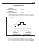
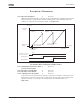
1002 Start frequency, auxiliary
drive 1
7 (P1.9.2)
The frequency of the drive controlled by the frequency converter must exceed
the limit defined with these parameters with 1 Hz before the auxiliary drive is started.
The 1 Hz overdraft makes a hysteresis to avoid unnecessary starts and stops. See
Figure 8-54. See also ID101 and ID102.