
Firmware Manual


9000X AF Drives
8-38 For more information visit: www.eaton.com
MN04004001E
August 2010
Description of Parameters
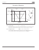
Figure 8-34: An Example of Joystick Hysteresis
In this example, the value of ID385 (Sleep limit) = 0
377
AI1 signal selection 234567 (P1.2.8, P1.2.3, P1.2.15, P1.2.2.1)
Connect the AI1 signal to the analog input of your choice with this parameter. For
more information about the TTF programming method, see Page 6-3.
384 AI1 joystick hysteresis 6 (P1.2.2.8)
This parameter defines the joystick hysteresis between 0 and 20%. When the joystick
or potentiometer control is turned from reverse to forward, the output frequency falls
linearly to the selected minimum frequency (joystick/potentiometer in middle
position) and stays there until the joystick/potentiometer is turned towards the
forward command. How much the joystick/potentiometer must be turned to start the
increase of the frequency towards the selected maximum frequency, is dependent on
the amount of joystick hysteresis defined with this parameter.
If the value of this parameter is 0, the frequency starts to increase linearly immediately
when the joystick/potentiometer is turned towards the forward command from the
middle position. When the control is changed from forward to reverse, the frequency
follows the same pattern the other way round. See Figure 8-34.
Frequency Reference
Hz
Reference
Scaling Max
ID304 = 70 Hz
Max Freq. ID102
= 50 Hz
Min Freq. ID101 =
Ref. Scaling Min
ID303 = 0 Hz
ID321
= 20%
ID322
= 90%
Joystick Hysteresis,
ID384 = 20%
REVERSE
50%
FORWARD
50%
From Reverse to Forward
From Forward to Reverse
Analog
Input (V/mA)
(0 – 10V/20 mA)
A
B