
Firmware Manual


9000X AF Drives
MN04004001E
For more information visit: www.eaton.com
8-35
August 2010
Description of Parameters
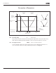
Figure 8-32: Place B Start Pulse/Stop Pulse
2 DIN4: closed contact = start — open contact = stop
DIN5: closed contact = start enabled —
open contact = start disabled and drive stopped if running
3 3-wire connection (pulse control):
DIN4: closed contact = start pulse
DIN5: open contact = stop pulse
(DIN3 can be programmed for reverse command) See Figure 8-32.
Selections 4 to 6 are used to exclude the possibility of an unintentional start when, for
example, power is connected, re-connected after a power failure, after a fault reset,
after the drive is stopped by Run Enable (Run Enable = False) or when the control
place is changed. The Start/Stop contact must be opened before the motor can be
started.
4 DIN4: closed contact = start forward (Rising edge required to start)
DIN5: closed contact = start reverse (Rising edge required to start)
5 DIN4: closed contact = start (Rising edge required to start) —
open contact = stop
DIN5: closed contact = reverse — open contact = forward
6 DIN4: closed contact = start (Rising edge required to start) —
open contact = stop
DIN5: closed contact = start enabled —
open contact = start disabled and drive stopped if running
364 Reference scaling, minimum
value, place B
3 (P1.2.18)
365 Reference scaling, maximum
value, place B
3 (P1.2.19)
See ID303 and ID304 above.
t
Output
Frequency
Stop Function
(ID506) = Coasting
If Start and Stop pulses are
simultaneous the Stop pulse
overrides the Start pulse.
REV
DIN4
Start
DIN5
Stop