
Firmware Manual


9000X AF Drives
MN04004001E
For more information visit: www.eaton.com
8-31
August 2010
Description of Parameters
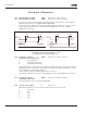
Figure 8-25: An Example of On/Off-Control
357 On/Off control low limit 6 (P1.3.4.14)
358 On/Off control high limit 6 (P1.3.4.15)
These parameters set the low and high limits of the signal selected with ID356. See
Figure 8-25.
359 PID controller minimum limit 5 (P1.2.30)
360 PID controller maximum limit 5 (P1.2.31)
With these parameters, you can set the minimum and maximum limits for the PID
controller output.
Limit setting: -1000.0% (of f
max
) < ID359 < ID360 < 1000.0% (of f
max
).
These limits are of importance for example when you define the gain, I-time and
D-time for the PID controller.
361 Free analog input, signal
selection
34 (P1.2.20, P1.2.17)
Selection of input signal for the free analog input (an input not used for a reference
signal):
0 Not in use
1 Voltage signal V
in
2 Current signal I
in
RO1
1
0
ID357
Time
ID358
In this example the programming of ID463 = B.1.
Analog Input (Selected with ID356)