
Firmware Manual


9000X AF Drives
8-28 For more information visit: www.eaton.com
MN04004001E
August 2010
Description of Parameters
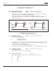
Figure 8-23: Control Place B with and without Reference Scaling
Left: ID344 = 0 (No reference scaling), Right: reference scaling
345 Reference scaling maximum
value, place B
57 (P1.2.36, P1.2.1.19)
You can choose a scaling range for the frequency reference from control place B
between the Minimum and Maximum frequency.
If no scaling is desired set the parameter value to 0.0.
In Figure 8-23, input AI1 with signal range 0 – 100% is selected for Place B reference.
346 Output freq. limit 2 supervision
function
34567 (P1.3.12, P1.3.4.3, P1.3.2.3)
0 No supervision
1 Low limit supervision
2 High limit supervision
3 Brake-on control (Application 6 only, see Page A-1.)
4 Brake-on/off control (Application 6 only, see Page A-1.)
If the output frequency goes under/over the set limit (ID347) this function generates a
warning message via the digital output DO1 or relay outputs RO1 or RO2 depending on:
1) the settings of ID312 to ID314 (Applications 3, 4, 5) or …
2) to which output the supervision signals (ID447 and ID448) are connected
(Applications 6 and 7).
347 Output frequency limit 2
supervision value
34567 (P1.3.13, P1.3.4.4, P1.3.2.4)
Selects the frequency value supervised by ID346. See Figure 8-16.
Output
Frequency
Output
Frequency
Max. Frequency ID102 Max. Frequency ID102
Min. Frequency ID101 Min. Frequency ID101
0
0
10
10
Analog
Input [V]
Analog
Input [V]
ID345
ID344