
Firmware Manual


9000X AF Drives
MN04004001E
For more information visit: www.eaton.com
8-25
August 2010
Description of Parameters
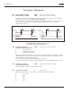
Table 8-11: Selections for ID332
326 Analog input AI2 custom
setting min.
34567 (P1.2.11, P1.2.23, P1.2.3.4)
327 Analog input AI2 custom
setting max.
34567 (P1.2.12, P1.2.24, P1.2.3.5)
These parameters set AI2 for any input signal span within 0 – 100%.
328 Analog input AI2 inversion 3457 (P1.2.13, P1.2.25, P1.2.3.6)
See ID323.
Note: In Application 3, AI2 is the place A frequency reference, if ID117 = 1 (default)
329 Analog input AI2 (I
in
) filter time 34567 (P1.2.14, P1.2.25, P1.2.3.2)
See ID324.
330 DIN5 function 5 (P1.2.3)
The digital input DIN5 has 14 possible functions. If it is not used, set the value to 0.
The selections are the same as in ID319 except:
13 Enable PID reference 2:
Contact open = PID controller reference selected with ID332
Contact closed = PID controller keypad reference 2 selected with
parameter R3.5
331 Motor potentiometer ramp
time
3567 (P1.2.22, P1.2.27, P1.2.1.2, P1.2.1.15)
Defines the speed of change of the motor potentiometer value.
332 PID controller reference signal
(Place A)
57 (P1.1.11)
Defines which frequency reference place is selected for the PID controller.
Application
57Select
0 AI1; terminals 2 – 3 AI1; terminals 2 – 3
1 AI2; terminals 4 – 5 AI2; terminals 4 – 5
2 PID ref. from menu M2,
parameter R34
AI3
3 Fieldbus reference
(FBProcessDataIN1)
AI4
4 Motor potentiometer
reference
PID ref. from menu M2,
parameter R34
5 — Fieldbus reference
(FBProcessDataIN1)
6 — Motor potentiometer
reference