
Firmware Manual


9000X AF Drives
8-24 For more information visit: www.eaton.com
MN04004001E
August 2010
Description of Parameters
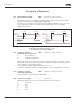
Figure 8-20: AI1 Signal Filtering
Table 8-10: Selections for Parameter ID325
Figure 8-21: Analog Input AI2 Scaling
324 AI1 signal filter time 34567 (P1.2.8, P1.2.20, P1.2.2.2)
When this parameter is given a value greater than 0, the function that filters out
disturbances from the incoming analog signal is activated.
A long filtering time makes the regulation response slower. See Figure 8-20.
325 Analog input AI2 signal range 34567 (P1.2.10, P1.2.22, P1.2.3.3)
Application
3, 4 5 6 7Select
0 0 – 20 mA 0 – 20 mA 0 – 100% 0 – 100%
1 4 – 20 mA 4 mA/
20 – 100%
20 – 100% 20 – 100%
2 Customized Customized -10 – +10V Customized
3 — — Customized —
Unfiltered Signal
Filtered Signal
%
100%
63%
t [s]
ID308
Output
Frequency
ID303
ID304
0
20 mA
AI2
(Term. 3,4)
ID327
ID326
4 mA
ID325 = Custom
ID325 = 0
AI2 = 0 – 100%
ID325 = 1
AI2 = 20 – 100%