
Firmware Manual


9000X AF Drives
8-20 For more information visit: www.eaton.com
MN04004001E
August 2010
Description of Parameters
Table 8-8: Output Signals Via DO1 and Output Relays RO1 and RO2, (Continued)
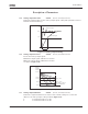
Figure 8-16: Output Frequency Supervision
Setting value Signal content
22 = Thermistor fault or warning
(Applications 3456)
The thermistor input of option board indicates
overtemperature. Fault or warning depending on ID732.
23 = Fieldbus input data
(Application 5)
23 = On/Off control (Application 6)
Fieldbus input data (FBFixedControlWord) to DO/RO.
Selects the analog input to be monitored. (ID356, ID357,
ID358 and ID463)
24 = Fieldbus input data 1
(Application 6)
Fieldbus data (FBFixedControlWord) to DO/RO
25 = Fieldbus input data 2
(Application 6)
Fieldbus data (FBFixedControlWord) to DO/RO
26 = Fieldbus input data 3
(Application 6)
Fieldbus data (FBFixedControlWord) to DO/RO
315 Output frequency limit
supervision function
234567 (P1.3.10, P1.3.4.1, P1.3.2.1)
0 No supervision
1 Low limit supervision
2 High limit supervision
3 Brake-on control (Application 6 only, see Page A-1.)
If the output frequency goes under/over the set limit (ID316) this function generates a
warning message via the digital output DO1 or via the relay outputs RO1 or RO2
depending on the settings of ID312 to ID314.
316 Output frequency limit
supervision value
234567 (P1.3.11, P1.3.4.2, P1.3.2.2)
Selects the frequency value supervised by ID315. See Figure 8-16.
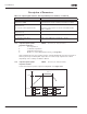
21 RO1Example:
22 RO1
23 RO1
21 RO1
22 RO1
23 RO1
21 RO1
22 RO1
23 RO1
t
f [Hz]
ID316
ID315 = 2