
Firmware Manual


9000X AF Drives
MN04004001E
For more information visit: www.eaton.com
8-9
August 2010
Description of Parameters
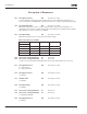
Table 8-5: Selections for ID171 and ID172
164
Motor control mode 1/2 6 (P1.2.7.22)
Contact is open = Motor control mode 1 is selected.
Contact is closed = Motor control mode 2 is selected.
See ID600 and ID521.
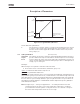
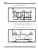
165 AI1 joystick offset 6 (P1.2.2.11)
Define the frequency zero point as follows: With this parameter being displayed, place
the potentiometer at the assumed zero point and press ENTER on the keypad. Note:
This will not change the reference scaling. Press the RESET button to change the
parameter value back to 0.00%.
166 AI2 joystick offset 6 (P1.2.3.11)
See ID165.
169 Fieldbus input data 4
(FBFixedControlWord, bit 6)
6 (P1.3.3.27)
170 Fieldbus input data 5
(FBFixedControlWord, bit 7)
6 (P1.3.3.28)
The data from the fieldbus (FBFixedControlWord) can be led to the digital outputs of
the frequency converter.
171
&172
Local & Remote Control Place
The active control place can be changed by pressing the LOC/REM button on the
keypad.
There are two different places which the frequency converter can be controlled from,
Local and Remote. For each control place the actual control source is selected with
this parameter, a different symbol will appear on the alphanumeric display:
Control source Symbol
I/O terminals
Keypad (panel)
Fieldbus
173
&174
Local & Remote reference
selection
234567
Defines which frequency reference source is selected when controlled from
the keypad.