
Firmware Manual


9000X AF Drives
8-8 For more information visit: www.eaton.com
MN04004001E
August 2010
Description of Parameters
Table 8-4: Selections for ID143
141
AI3 signal selection 567 (P1.2.38, P1.2.4.1)
Connect the AI3 signal to the analog input of your choice with this parameter. For
more information, see Page 6-3, “Terminal to Function” (TTF) programming principle.
142 AI3 signal filter time 567 (P1.2.41, P1.2.4.2)
When this parameter is given a value greater than 0, the function that filters out
disturbances from the incoming analog signal is activated. A long filtering time makes
the regulation response slower. See ID324.
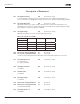
143 AI3 signal range 567 (P1.2.39, P1.2.4.3)
With this parameter you can select the AI3 signal range.
Application
567Select
0 0 – 100% 0 – 100% 0 – 100%
1 20 – 100% 20 – 100% 20 – 100%
2 — -10 – +10V Customized
3 — Customized
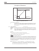
144 AI3 custom setting minimum 67 (P1.2.4.4)
145 AI3 custom setting maximum 67 (P1.2.4.5)
Set the custom minimum and maximum levels for the AI3 signal from 0 to 100%.
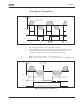
151 AI3 signal inversion 567 (P1.2.40, P1.2.4.6)
0 = No inversion
1 = Signal inverted
152
AI4 signal selection 567 (P1.2.42, P1.2.5.1)
See ID141.
153 AI4 filter time 567 (P1.2.45, P1.2.5.2)
See ID142.
154 AI4 signal range 567 (P1.2.43, P1.2.5.3)
See ID143.
155 AI4 custom setting minimum 67 (P1.2.5.4)
156 AI4 custom setting maximum 67 (P1.2.5.5)
See ID144 and ID145.
162 AI4 signal inversion 567 (P1.2.44, P1.2.5.6)
See ID151.