
Firmware Manual


9000X AF Drives
7-20 For more information visit: www.eaton.com
MN04004001E
August 2010
Pump and Fan Control Application
Analog Output 2 (Control Keypad: Menu M1
➔
G1.3.4)
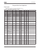
Table 7-13: Output Signals, Analog Output 2 — G1.3.4
Analog Output 3 (Control Keypad: Menu M1
➔
G1.3.5)
Table 7-14: Output Signals, Analog Output 3 — G1.3.5
Code Parameter Min. Max. Unit Default Cust ID Note
P1.3.4.1 Analog output 2
signal selection
AnOUT:01 AnOUT:E.10 AnOUT:0.1 471
P1.3.4.2 Analog output 2
function
0 14 0 472 See P1.3.3.2
P1.3.4.3 Analog output 2
filter time
0.00 10.00 s 1.00 473 0.00 = No filtering
P1.3.4.4 Analog output 2
inversion
0 1 0 474 0 = Not inverted
1 = Inverted
P1.3.4.5 Analog output 2
minimum
0 1 0 475 0 = 0 mA
1 = 4 mA
P1.3.4.6 Analog output 2
scale
10 1000 % 100 476
P1.3.4.7 Analog output 2
offset
-100.00 100.00 % 0.00 477
Code Parameter Min. Max. Unit Default Cust ID Note
P1.3.5.1 Analog output 3
signal selection
AnOUT:01 AnOUT:E.10 AnOUT:0.1 478
P1.3.5.2 Analog output 3
function
0 14 0 479 See P1.3.3.2
P1.3.5.3 Analog output 3
filter time
0.00 10.00 s 1.00 480 0.00 = No filtering
P1.3.5.4 Analog output 3
inversion
0 1 0 481 0 = Not inverted
1 = Inverted
P1.3.5.5 Analog output 3
minimum
0 1 0 482 0 = 0 mA
1 = 4 mA
P1.3.5.6 Analog output 3
scale
10 1000 % 100 483
P1.3.5.7 Analog output 3
offset
-100.00 100.00 % 0.00 484