
Firmware Manual


9000X AF Drives
MN04004001E
For more information visit: www.eaton.com
7-19
August 2010
Pump and Fan Control Application
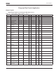
Table 7-11: Output Signals, Limit Settings — G1.3.2 (Continued)
Analog Output 1 (Control Keypad: Menu M1
➔
G1.3.3)
Table 7-12: Output Signals, Analog Output 1 — G1.3.3
Code Parameter Min. Max. Unit Default Cust ID Note
P1.3.2.12 FC temperature
supervised value
-10 75 ∞C 40 355
P1.3.2.13 Supervised analog
input
0 1 0 372 0 = AI1
1 = AI2
P1.3.2.14 Analog input
supervision limit
0 2 0 373 0 = No limit
1 = Low limit supervision
2 = High limit supervision
P1.3.2.15 Analog input
supervised value
0.00 100.00 % 0.00 374
Code
Parameter Min. Max. Unit Default Cust ID Note
P1.3.3.1 Analog output
signal selection
AnOUT:0.1 AnOUT:E.10 AnOUT:A.1 464
P1.3.3.2 Analog output
function
0 14 1 307 0 = Not used
1 = Output freq. (0 – f
max
)
2 = Freq. reference (0 – f
max
)
3 = Motor speed (0 – Motor
nominal speed)
4 = Motor current (0 – I
nMotor
)
5 = Motor torque (0 – T
nMotor
)
6 = Motor power (0 – P
nMotor
)
7 = Motor voltage (0 – V
nMotor
)
8 = DC-link volt (0 – 1000V)
9 = PID controller ref. value
10 = PID contr. act.value 1
11 = PID contr. act.value 2
12 = PID contr. error value
13 = PID controller output
14 = PT100 temperature
P1.3.3.3 Analog output
filter time
0.00 10.00 s 1.00 308 0.00 = No filtering
P1.3.3.4 Analog output
inversion
0 1 0 309 0 = Not inverted
1 = Inverted
P1.3.3.5 Analog output
minimum
0 1 0 310 0 = 0 mA
1 = 4 mA
P1.3.3.6 Analog output
scale
10 1000 % 100 311
P1.3.3.7 I
out
offset -100.00 100.00 % 0.00 375