
Firmware Manual


9000X AF Drives
MN04004001E
For more information visit: www.eaton.com
7-13
August 2010
Pump and Fan Control Application
Input Signals
Basic Settings (Control Keypad: Menu M1
➔
G1.2.1)
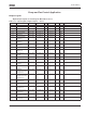
Table 7-4: Input Signals, Basic Settings — G1.2.1
Code Parameter Min. Max. Unit Default Cust ID Note
P1.2.1.1
PID Reference 2 0 7 7 371 0 = AI1
1 = AI2
2 = AI3
3 = AI4
4 = PID reference 1 from keypad
5 = Fieldbus reference
(FBProcessDataIN3)
6 = Motor potentiometer
7 = PID reference 2 from keypad
P1.2.1.2 PID error value
inversion
0 1 0 340 0 = No inversion
1 = Inversion
P1.2.1.3 PID reference
rising time
0.0 100.0 5.0 341 Time for reference value to
change from 0% to 100%
P1.2.1.4 PID reference
falling time
0.0 100.0 5.0 342 Time for reference value to
change from 100% to 0%
P1.2.1.5
PID actual value
selection
0 7 0 333 0 = Actual value 1
1 = Actual 1 + Actual 2
2 = Actual 1 – Actual 2
3 = Actual 1 * Actual 2
4 = Max (Actual 1, Actual 2)
5 = Min (Actual 1, Actual 2)
6 = Mean (Actual 1, Actual 2)
7 = Sqrt (Act 1) + Sqrt (Act 2)
P1.2.1.6
Actual value 1
selection
0 5 2 334 0 = Not used
1 = AI1
2 = AI2
3 = AI3
4 = AI4
5 = Fieldbus
P1.2.1.7
Actual value 2
selection
0 5 0 335 0 = Not used
1 = AI1
2 = AI2
3 = AI3
4 = AI4
5 = Fieldbus
P1.2.1.8 Actual value 1
minimum scale
-1600.0 1600.0 % 0.0 336 0.0 = No minimum scaling
P1.2.1.9 Actual value 1
maximum scale
-1600.0 1600.0 % 100.0 337 100.0 = No maximum scaling
P1.2.1.10 Actual value 2
minimum scale
-1600.0 1600.0 % 0.0 338 0.0 = No minimum scaling
P1.2.1.11 Actual value 2
maximum scale
-1600.0 1600.0 % 100.0 339 100.0 = No maximum scaling
P1.2.1.12 Motor
potentiometer ramp
time
0.1 2000.0 Hz/s 10.0 331