
Firmware Manual


9000X AF Drives
MN04004001E
For more information visit: www.eaton.com
7-11
August 2010
Pump and Fan Control Application
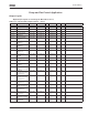
Table 7-2: Monitoring Values (Continued)
Basic Parameters (Control Keypad: Menu M1
➔
G1.1)
Table 7-3: Basic Parameters — G1.1
Code Parameter Unit ID Description
V1.17 Analog input 4 V/mA 28 AI4 input value
V1.18 PID Reference % 20 In % of the max. frequency
V1.19 PID Actual value % 21 In % of the max actual value
V1.20 PID Error value % 22 In % of the max error value
V1.21 PID Output % 23 In % of the max output value
V1.22 Running auxiliary drives 30 Number of running auxiliary drives
V1.23 Special display for actual
value
29 See parameters 1.9.29 to 1.9.31
V1.24 PT-100 temperature Cº Highest temperature of used PT100
inputs
G1.25 Multimonitoring items Displays 3 selectable monitor. values
Code Parameter Min. Max. Unit Default Cust ID Note
P1.1.1 Min frequency 0.00 Par. 1.1.2 Hz 0.00 101
P1.1.2 Max frequency Par. 1.1.1 320.00 Hz 60.00 102 NOTE: If f
max
> than the motor
synchronous speed, check
suitability for motor and drive
system.
P1.1.3 Acceleration time 1 0.1 3000.0 s 1.0 103
P1.1.4 Deceleration time 1 0.1 3000.0 s 1.0 104
P1.1.5 Current limit 0.4 x I
H
2 x I
H
AI
L
107
P1.1.6
Nominal voltage of
the motor
180 690 V P: 230V
P: 460V
P: 575V
110
P1.1.7
Nominal frequency
of the motor
30.00 320.00 Hz 60.00 111 Check the rating plate of the
motor.
P1.1.8
Nominal speed of
the motor
300 20 000 rpm 1720 112 The default applies for a 4-pole
motor and a nominal size
frequency converter.
P1.1.9
Nominal current of
the motor
0.4 x I
H
2 x I
H
AI
H
113 Check the rating plate of the
motor.
P1.1.10
Power factor 0.30 1.00 0.85 120 Check the rating plate of the
motor.
P1.1.11
Local control place 1 3 2 171 1 = I/O Terminal
2 = Keypad
3 = Fieldbus
P1.1.12
Remote control
place
1 3 1 172 1 = I/O Terminal
2 = Keypad
3 = Fieldbus