9000X AF Drives Application Manual Effective August 2010 Supersedes January 2010
9000X AF Drives August 2010 Important Notice — Please Read The product discussed in this literature is subject to terms and conditions outlined in Eaton Electrical Inc. selling policies. The sole source governing the rights and remedies of any purchaser of this equipment is the relevant Eaton Electrical Inc. selling policy.
9000X AF Drives August 2010 Table of Contents ii CHAPTER — LIST OF FIGURES. . . . . . . . . . . . . . . . . . . . . . . . . . . . . . . . . . . . . . . . . . . . . . CHAPTER — LIST OF TABLES. . . . . . . . . . . . . . . . . . . . . . . . . . . . . . . . . . . . . . . . . . . . . . . CHAPTER — SAFETY. . . . . . . . . . . . . . . . . . . . . . . . . . . . . . . . . . . . . . . . . . . . . . . . . . . . . . Definitions and Symbols . . . . . . . . . . . . . . . . . . . . . . . . . . . . . . . . . . . . . . .
9000X AF Drives August 2010 Table of Contents, continued MN04004001E CHAPTER 8 — DESCRIPTION OF PARAMETERS . . . . . . . . . . . . . . . . . . . . . . . . . . . . . . . . Introduction . . . . . . . . . . . . . . . . . . . . . . . . . . . . . . . . . . . . . . . . . . . . . . . . . . . . . . . . . . Keypad Control Parameters . . . . . . . . . . . . . . . . . . . . . . . . . . . . . . . . . . . . . . . . . . . . . 8-1 8-1 8-86 APPENDIX A — ADDITIONAL INFORMATION. . . . . . . . . . . . . . . . . . . . . .
9000X AF Drives August 2010 List of Figures Defining Input/Output — Function . . . . . . . . . . . . . . . . . . . . . . . . . . . . . . . . . . . . . . . . . . . Defining Input/Output — Values . . . . . . . . . . . . . . . . . . . . . . . . . . . . . . . . . . . . . . . . . . . . . Screenshot of 9000X Drive Programming Tool; Entering the Address Code . . . . . . . . . 2-Pump Autochange System Principal Control Diagram . . . . . . . . . . . . . . . . . . . . . . . . .
9000X AF Drives August 2010 List of Figures, continued Reducing Acceleration and Deceleration Times . . . . . . . . . . . . . . . . . . . . . . . . . . . . . . . . . Reducing Torque Supervision Limit . . . . . . . . . . . . . . . . . . . . . . . . . . . . . . . . . . . . . . . . . . . Digital Outputs 1 and 2, On- and Off-Delays . . . . . . . . . . . . . . . . . . . . . . . . . . . . . . . . . . . . An Example of Adjust Input . . . . . . . . . . . . . . . . . . . . . . . . . . . . . . . . . . . . . . . . .
9000X AF Drives August 2010 List of Tables, continued Table 3-1: Local/Remote Application Default I/O Configuration . . . . . . . . . . . . . . . . . . . Table 3-2: Monitoring Values . . . . . . . . . . . . . . . . . . . . . . . . . . . . . . . . . . . . . . . . . . . . . . . Table 3-3: Basic Parameters — G1.1 . . . . . . . . . . . . . . . . . . . . . . . . . . . . . . . . . . . . . . . . . . Table 3-4: Input Signals — G1.2 . . . . . . . . . . . . . . . . . . . . . . . . . . . . . . . . . . . . . . . . . .
000X AF Drives August 2010 List of Tables, continued Table 6-21: Drive Control Parameters — G1.4 . . . . . . . . . . . . . . . . . . . . . . . . . . . . . . . . . . Table 6-22: Skip Frequency Parameters — G1.5 . . . . . . . . . . . . . . . . . . . . . . . . . . . . . . . . . Table 6-23: Motor Control Parameters — G1.6 . . . . . . . . . . . . . . . . . . . . . . . . . . . . . . . . . . Table 6-24: Protections — G1.7 . . . . . . . . . . . . . . . . . . . . . . . . . . . . . . . . . . . . . . . . . . . . . .
9000X AF Drives August 2010 Safety Definitions and Symbols WARNING This symbol indicates high voltage. It calls your attention to items or operations that could be dangerous to you and other persons operating this equipment. Read the message and follow the instructions carefully. This symbol is the “Safety Alert Symbol.” It occurs with either of two signal words: CAUTION or WARNING, as described below.
9000X AF Drives August 2010 Cautions and Notices Read this manual thoroughly and make sure you understand the procedures before you attempt to install, set up, or operate this 9000X AF Drives from Eaton’s electrical sector. Cautions CAUTION Be ABSOLUTELY sure not to connect two functions to one and same output in order to avoid function overruns and to ensure flawless operation. CAUTION The calculated model does not protect the motor if the airflow to the motor is reduced by blocked air intake grill.
9000X AF Drives August 2010 x For more information visit: www.eaton.
9000X AF Drives August 2010 Chapter 1 — Basic Application Introduction The Basic Application is easy to use with a minimum number of parameters. It operates like the default setup of the Standard Application. It is the default setting on delivery from the factory. If any configuration changes are needed, select the Standard Application in menu M5. Fieldbus control is not available in the Basic Application, but fieldbus monitoring is the same as the Standard Application.
9000X AF Drives August 2010 Basic Application Control I/O Reference potentiometer 1 – 10 kW mA READY RUN 220V AC Table 1-1: Basic Application Default I/O Configuration Terminal OPTA1 1 +10Vref 2 AI1+ Signal Description Reference output Analog input, voltage range 0 – 10V DC I/O Ground Analog input, current range 0 – 20 mA Voltage for potentiometer, etc.
9000X AF Drives August 2010 Basic Application Basic Application — Parameter Lists On the next pages you will find the lists of parameters within the respective parameter groups. The parameter descriptions are given in Chapter 8.
9000X AF Drives August 2010 Basic Application Basic Parameters (Control Keypad: M1 ➔ G1.1) Table 1-3: Basic Parameters — G1 Code Parameter Min. P1.1 P1.2 Min frequency Max frequency 0.00 Par. 1.2 Par. 1.1 320.00 Hz Hz 0.00 60.00 101 102 P1.3 P1.4 P1.5 P1.6 Acceleration time 1 Deceleration time 1 Current limit Nominal voltage of the motor 0.1 0.1 0.1 x IH 180 3000.0 3000.0 2 x IH 690 s s A V 103 104 107 110 P1.7 Nominal frequency of the motor Nominal speed of the motor 30.00 320.
9000X AF Drives August 2010 Basic Application Keypad Control (Control Keypad: Menu M2) The parameters for the selection of control place and direction on the keypad are listed below. See the Keypad Control Menu in the 9000X AF Drives User Manual. Table 1-4: Keypad Control Parameters — M2 Code Parameter Min. Max. R1.1 P1.2 Keypad reference Direction (on keypad) Par. 1.1 Par. 1.2 0 1 R1.3 Stop button 0 P2.4 Operate menu hide 0 Unit Default Cust ID Note 60.
9000X AF Drives August 2010 1-6 For more information visit: www.eaton.
9000X AF Drives August 2010 Chapter 2 — Standard Application Introduction Select the Standard Application in menu M5. See Chapter 5 of the 9000X AF Drives User Manual. The Standard Application is typically used in pump and fan applications and conveyors for which the Basic Application is too limited but where no special features are needed. ● The Standard Application has the same I/O signals and the same control logic as the Basic Application.
9000X AF Drives August 2010 Standard Application Control I/O Table 2-1: Standard Application Default I/O Configuration Reference potentiometer 1 – 10 kW mA READY RUN 220V AC Terminal OPTA1 1 +10Vref 2 AI1+ Signal Description Reference output Analog input, voltage range 0 – 10V DC I/O Ground Analog input, current range 0 – 20 mA Voltage for potentiometer, etc. Voltage input frequency reference Voltage for switches, etc. max 0.
9000X AF Drives August 2010 Standard Application Standard Application — Parameter Lists On the next pages you will find the lists of parameters within the respective parameter groups. The parameter descriptions are given in Chapter 8. The descriptions are arranged according to the ID number of the parameter.
9000X AF Drives August 2010 Standard Application Table 2-2: Monitoring Values (Continued) Code Parameter Unit ID Description V1.16 Analog Iout mA 26 AO1 M1.17 Monitoring items Displays three selectable monitoring values Basic Parameters (Control Keypad: Menu M1 ➔ G1.1) Table 2-3: Basic Parameters — G1.1 Code Parameter Min. Max. P1.1.1 P1.1.2 Min frequency Max frequency 0.00 Par. 1.1.1 Par. 1.1.2 Hz 320.00 Hz 0.00 60.00 101 102 P1.1.3 P1.1.4 P1.1.5 P1.1.
9000X AF Drives August 2010 Standard Application Input Signals (Control Keypad: Menu M1 ➔ G1.2) Table 2-4: Input Signals — G1.2 Code Parameter Min. Max. Start/Stop logic 0 6 P1.2.2 DIN3 function 0 P1.2.3 Current reference offset Reference scaling minimum value P1.2.5 P1.2.6 P1.2.1 P1.2.4 ID Note 0 300 7 1 301 0 1 1 302 0.00 Par. 1.2.5 Hz 0.00 303 Reference scaling maximum value 0.00 320.00 0.00 304 Reference inversion 0 1 0 305 0.00 10.00 0.10 A.1 306 377 A.
9000X AF Drives August 2010 Standard Application Table 2-5: Output Signals — G1.3 (Continued) Code Parameter Min. Max. P1.3.4 Analog output inversion Analog output minimum Analog output scale Digital output 1 function 0 1 0 1 10 0 1000 16 P1.3.5 P1.3.6 P1.3.7 P1.3.8 P1.3.9 P1.3.10 P1.3.11 P1.3.12 P1.3.13 P1.3.14 P1.3.15 P1.3.16 P1.3.
9000X AF Drives August 2010 Standard Application Drive Control Parameters (Control Keypad: Menu M1 ➔ G1.4) Table 2-6: Drive Control Parameters — G1.4 Code Parameter Min. Max. Unit Default Cust ID Note P1.4.1 Ramp 1 shape 0.0 10.0 s 0.0 500 P1.4.2 Ramp 2 shape 0.0 10.0 s 0.0 501 0 = Linear >0 = S-curve ramp time 0 = Linear >0 = S-curve ramp time P1.4.3 P1.4.4 P1.4.5 Acceleration time 2 Deceleration time 2 Brake chopper 0.1 0.1 0 3000.0 3000.0 4 s s 10.0 10.0 0 502 503 504 P1.
9000X AF Drives August 2010 Standard Application Motor Control Parameters (Control Keypad: Menu M1 ➔ G1.6) Table 2-8: Motor Control Parameters — G1.6 Code Parameter Min. Max. ID Note Motor control mode 0 1/6 0 600 1 0 109 0 3 0 108 SVX: 0 = Frequency control 1 = Speed control Additionally for SPX: 2 = Torque control 3 = Closed loop speed ctrl 4 = Closed loop torque ctrl 0 = Not used 1 = Automatic torque boost 0 = Linear 1 = Squared 2 = Programmable 3 = Linear with flux optim. P1.6.
9000X AF Drives August 2010 Standard Application Motor Control Parameters — G1.6 Code Parameter Min. Max. Closed Loop parameter group 1.6.14 (SPX only) (Continued) P1.6.14.9 0-speed time at start 0 32000 P1.6.14.10 0-speed time at stop 0 32000 P1.6.14.11 Start-up torque 0 3 P1.6.14.12 P1.6.14.13 P1.6.14.15 P1.6.14.17 Start-up torque FWD Start-up torque REV Encoder filter time Current control P gain -300.0 -300.0 0 0.00 300.0 300.0 1000 100.
9000X AF Drives August 2010 Standard Application Table 2-9: Protections — G1.7 (Continued) Code Parameter Min. Max. Unit Default Cust ID Note P1.7.14 Stall current 0.1 IL 710 P1.7.15 Stall time limit P1.7.16 Stall frequency limit 1.00 1.0 15.00 25.0 711 712 P1.7.17 Underload protection 0 InMotor A x2 120.00 s Par. Hz 1.1.2 3 0 713 P1.7.18 Field weakening area load P1.7.19 Zero frequency load P1.7.20 Underload protection time limit P1.7.
9000X AF Drives August 2010 Standard Application Keypad Control (Control Keypad: Menu M2) The parameters for the selection of control place and direction on the keypad are listed below. See the Keypad control menu in the 9000X AF Drives User Manual. Table 2-11: Keypad Control Parameters — M2 Code Parameter Min. Max. P2.1 Control place 0 3 R2.1 P2.3 Unit Default Cust ID Note 0 1685 0 = Keypad L/R 1 = Local 2 = Remote 3 = I/O force Keypad reference Par. 1.1.1 Par. 1.1.
9000X AF Drives August 2010 2-12 For more information visit: www.eaton.
9000X AF Drives August 2010 Chapter 3 — Local/Remote Control Application Introduction Select the Local/Remote Control Application in menu M5. See Chapter 5 of the 9000X AF Drives User Manual. ● The Local/Remote Application utilizes digital input DIN6 to select between Local and Remote control. For each control location, the frequency can be selected from either the keypad, I/O terminals, or fieldbus. ● All outputs are freely programmable.
9000X AF Drives August 2010 Local/Remote Control Application Control I/O Table 3-1: Local/Remote Application Default I/O Configuration Remote Reference Pot.
9000X AF Drives August 2010 Local/Remote Control Application Local/Remote Control Application — Parameter Lists On the next pages you will find the lists of parameters within the respective parameter groups. The parameter descriptions are given in Chapter 8.
9000X AF Drives August 2010 Local/Remote Control Application Basic Parameters (Control Keypad: Menu M1 ➔ G1.1) Table 3-3: Basic Parameters — G1.1 Code Parameter Min. P1.1.1 P1.1.2 Min frequency Max frequency 0.00 Par. 1.1.2 Hz Par. 1.1.1 320.00 Hz 0.00 60.00 101 102 P1.1.3 P1.1.4 P1.1.5 P1.1.6 Acceleration time 1 Deceleration time 1 Current limit Nominal voltage of the motor 0.1 0.1 0.1 x IH 180 3000.0 3000.0 2 x IH 690 s s A V 103 104 107 110 P1.1.
9000X AF Drives August 2010 Local/Remote Control Application Input Signals (Control Keypad: Menu M1 ➔ G1.2) Table 3-4: Input Signals — G1.2 Code Parameter Min. Max. P1.2.1 Start/Stop logic selection 0 8 Unit Default Cust 0 ID Note 300 0 1 2 3 4 5 6 7 8 P1.2.2 DIN3 function 0 P1.2.3 AI1 signal selection 0 P1.2.4 AI1 signal inversion 0 1 P1.2.5 AI1 signal filter time 0.00 10.00 P1.2.6 AI2 signal selection 0 P1.2.7 AI2 signal range 0 P1.2.8 AI2 custom setting 0.
9000X AF Drives August 2010 Local/Remote Control Application Table 3-4: Input Signals — G1.2 (Continued) Code Parameter P1.2.10 AI2 signal inversion 0 1 P1.2.11 AI2 signal filter time 0.00 10.00 Min. Max. Unit s Default Cust ID Note 0 328 Analog input 2 reference inversion yes/no 0.
9000X AF Drives August 2010 Local/Remote Control Application Output Signals (Control Keypad: Menu M1 ➔ G1.3) Table 3-5: Output Signals — G1.3 Code P1.3.1 P1.3.2 P1.3.3 P1.3.4 P1.3.5 P1.3.6 P1.3.7 P1.3.8 P1.3.9 P1.3.10 MN04004001E Parameter Min. Max. AO1 signal selection Analog output function 0 0 8 Analog output filter time Analog output inversion Analog output minimum Analog output scale Digital output 1 function 0.00 10.00 0 Unit ID Note A.1 464 1 307 1.
9000X AF Drives August 2010 Local/Remote Control Application Output Signals — G1.3 (Continued) Code Parameter P1.3.11 Max. Unit Default Output frequency 0.00 limit 1; Supervision value 320.00 Hz 0.00 316 P1.3.12 Output frequency 0 limit 2 supervision 2 0 346 P1.3.13 Output frequency 0.00 limit 2; Supervision value 320.00 0.00 347 P1.3.14 Torque limit supervision function 0 2 0 348 P1.3.15 Torque limit supervision value 0.0 200.0 0.0 349 P1.3.
9000X AF Drives August 2010 Local/Remote Control Application Drive Control Parameters (Control Keypad: Menu M1 ➔ G1.4) Table 3-6: Drive Control Parameters — G1.4 Code Parameter Min. Max. Unit Default P1.4.1 Ramp 1 shape 0.0 10.0 s P1.4.2 Ramp 2 shape 0.0 10.0 P1.4.3 Acceleration time 2 0.1 P1.4.4 Deceleration time 2 P1.4.5 ID Note 0.0 500 0 = Linear >0 = S-curve ramp time s 0.0 501 0 = Linear >0 = S-curve ramp time 3000.0 s 10.0 502 0.1 3000.0 s 10.
9000X AF Drives August 2010 Local/Remote Control Application Skip Frequency Parameters (Control Keypad: Menu M1 ➔ G1.5) Table 3-7: Skip Frequency Parameters — G1.5 Code Parameter P1.5.1 Min. Max. Unit Default Cust ID Skip frequency 0.00 range 1 low limit par. 1.5.2 Hz 0.00 509 P1.5.2 Skip frequency range 1 high limit 0.00 par. 1.1.2 Hz 0.0 510 P1.5.3 Skip frequency 0.00 range 2 low limit par. 1.5.2 Hz 0.00 511 P1.5.4 Skip frequency range 2 high limit 0.00 par. 1.1.2 Hz 0.
9000X AF Drives August 2010 Local/Remote Control Application Table 3-8: Motor Control Parameters — G1.6 (Continued) Code Parameter Min. Max. Unit Default P1.6.8 Output voltage 0.00 at zero frequency 40.00 % P1.6.9 Switching frequency 1.0 Varies kHz P1.6.10 Overvoltage controller 0 P1.6.11 Undervoltage controller P1.6.12 P1.6.13 Cust ID Note 1.
9000X AF Drives August 2010 Local/Remote Control Application Protections (Control Keypad: Menu M1 ➔ G1.7) Table 3-9: Protections — G1.7 Code Parameter Min. Max. P1.7.1 Response to reference fault 0 5 P1.7.2 4mA reference fault frequency 0.00 Par. 1.1.2 P1.7.3 Response to external fault 0 P1.7.4 Input phase supervision P1.7.5 ID Note 0 700 0 = No response 1 = Warning 2 = Warning+Previous Freq. 3 = Wrng+PresetFreq 1.7.2 4 = Fault.stop acc. to 1.4.7 5 = Fault.stop by coasting 0.
9000X AF Drives August 2010 Local/Remote Control Application Table 3-9: Protections — G1.7 (Continued) Code Parameter Min. Max. Unit Default P1.7.14 Stall current 0.1 InMotor x 2 A IL 710 P1.7.15 Stall time limit 1.00 120.00 s 15.00 711 P1.7.16 Stall frequency limit 1.0 Par. 1.1.2 Hz 25.0 712 P1.7.17 Underload protection 0 3 0 713 P1.7.18 Field weakening area load 10 150 % 50 714 P1.7.19 Zero frequency load 5.0 150.0 % 10.0 715 P1.7.
9000X AF Drives August 2010 Local/Remote Control Application Table 3-10: Autorestart Parameters — G1.8 (Continued) Code Parameter Min. Max. Unit Default Cust ID P1.8.8 Number of tries 0 after motor temp fault trip 10 0 726 P1.8.9 Number of tries after external fault trip 0 10 0 725 P1.8.10 Number of tries after underload fault trip 0 10 0 738 Note Keypad Control (Control Keypad: Menu M2) The parameters for the selection of control place and direction on the keypad are listed below.
9000X AF Drives August 2010 Chapter 4 — Multi-Step Speed Control Application Introduction Select the Multi-Step Speed Control Application in menu M5. See Chapter 5 of the 9000X AF Drives User Manual. The Multi-Step Speed Control Application can be used in applications where fixed speeds are needed. Totally 15 + 2 different speeds can be programmed: one basic speed, 15 multi-step speeds and one jogging speed. The speed steps are selected with digital signals DIN3, DIN4, DIN5 and DIN6.
9000X AF Drives August 2010 Multi-Step Speed Control Application Control I/O Table 4-1: Multi-Step Speed Control Application Default I/O Configuration Remote reference pot. 1 – 10 kW Basic Reference (optional) mA READY RUN 220V AC Terminal OPTA1 1 +10Vref 2 AI1+ Signal Description Reference output Analog input, voltage range 0 – 10V DC I/O Ground Analog input, current range 0 – 20 mA Voltage for potentiometer, etc.
9000X AF Drives August 2010 Multi-Step Speed Control Application Multi-Step Speed Control Application — Parameter Lists On the next pages you will find the lists of parameters within the respective parameter groups. The parameter descriptions are given in Chapter 8.
9000X AF Drives August 2010 Multi-Step Speed Control Application Basic Parameters (Control Keypad: Menu M1 ➔ G1.1) Table 4-3: Basic Parameters — G1.1 Code Parameter Min. Max. Unit Default P1.1.1 P1.1.2 Min frequency Max frequency 0.00 Par. 1.1.2 Hz Par. 1.1.1 320.00 Hz 0.00 60.00 P1.1.3 P1.1.4 P1.1.5 P1.1.6 Acceleration time 1 Deceleration time 1 Current limit Nominal voltage of the motor 0.1 0.1 0.4 x IH 180 3000.0 3000.0 2 x IH 690 s s A V P1.1.
9000X AF Drives August 2010 Multi-Step Speed Control Application Table 4-3: Basic Parameters — G1.1 (Continued) Code Parameter Min. Max. Unit Default P1.1.24 P1.1.25 P1.1.26 Preset speed 7 Preset speed 8 Preset speed 9 0.00 0.00 0.00 Par. 1.1.2 Par. 1.1.2 Par. 1.1.2 Hz Hz Hz P1.1.27 P1.1.28 Preset speed 10 Preset speed 11 0.00 0.00 Par. 1.1.2 Par. 1.1.2 P1.1.29 P1.1.30 P1.1.31 P1.1.32 Preset speed 12 Preset speed 13 Preset speed 14 Preset speed 15 0.00 0.00 0.00 0.00 Par. 1.1.2 Par. 1.1.
9000X AF Drives August 2010 Multi-Step Speed Control Application Table 4-4: Input Signals — G1.2 (Continued) Code Parameter P1.2.5 Max. Unit Default AI1 custom setting 0.00 minimum 100.00 % P1.2.6 AI1 custom setting 0.00 maximum 100.00 % P1.2.7 AI1 signal inversion 0 1 P1.2.8 AI1 signal filter time 0.00 10.00 P1.2.9 AI2 signal selection 0 P1.2.10 AI2 signal range 0 P1.2.11 AI2 custom setting 0.00 minimum 100.00 P1.2.12 AI2 custom setting 0.00 maximum 100.00 P1.2.
9000X AF Drives August 2010 Multi-Step Speed Control Application Output Signals (Control Keypad: Menu M1 ➔ G1.3) Table 4-5: Output Signals — G1.3 Code P1.3.1 Parameter Min. AO1 signal selection 0 Max. Unit Default Cust ID Note A.1 464 1 307 1.00 308 TTF programming method used. See Page 6-3. 0 = Not used 1 = Output freq. (0 – fmax) 2 = Freq.
9000X AF Drives August 2010 Multi-Step Speed Control Application Table 4-5: Output Signals — G1.3 (Continued) Code Parameter Min. Max. P1.3.11 Output frequency limit 1; Supervision value Output frequency limit 2 supervision 0.00 320.00 Hz 0.00 316 0 2 0 346 Output frequency limit 2; Supervision value Torque limit supervision function 0.00 320.00 Hz 0.00 347 0 2 0 348 Torque limit supervision value Reference limit supervision function 0.0 200.
9000X AF Drives August 2010 Multi-Step Speed Control Application Drive Control Parameters (Control Keypad: Menu M1 ➔ G1.4) Table 4-6: Drive Control Parameters — G1.4 Code Parameter Min. Max. Unit Default P1.4.1 Ramp 1 shape 0.0 10.0 s P1.4.2 Ramp 2 shape 0.0 10.0 s P1.4.3 P1.4.4 P1.4.5 Acceleration time 2 Deceleration time 2 Brake chopper 0.1 0.1 0 P1.4.6 Start function P1.4.7 P1.4.8 P1.4.9 ID Note 0.0 500 0.
9000X AF Drives August 2010 Multi-Step Speed Control Application Motor Control Parameters (Control Keypad: Menu M1 ➔ G1.6) Table 4-8: Motor Control Parameters — G1.6 Code Parameter Min. Max. P1.6.1 Motor control mode 0 1/6 0 600 P1.6.2 V/Hz optimization 0 1 0 109 P1.6.3 V/Hzf ratio selection 0 3 0 108 P1.6.4 P1.6.5 8.00 10.00 320.00 200.00 60.00 100.00 602 603 0.00 Par. 1.6.4 Hz 60.00 604 0.00 100.00 % 100.00 605 0.00 40.00 % 1.30 606 P1.6.
9000X AF Drives August 2010 Multi-Step Speed Control Application Table 4-8: Motor Control Parameters — G1.6 (Continued) Code Parameter Min. Closed Loop parameter group 1.6.14 (SPX only) P1.6.14.1 Magnetizing current 0.00 P1.6.14.2 Speed control P gain 0 P1.6.14.3 Speed control I time 0.0 P1.6.14.5 Acceleration 0.00 compensation P1.6.14.6 Slip adjust 0 P1.6.14.7 Magnetizing current at MotCurr start Min P1.6.14.8 Magnetizing time at 0.0 start P1.6.14.9 0-speed time at start 0 P1.6.14.
9000X AF Drives August 2010 Multi-Step Speed Control Application Protections (Control Keypad: Menu M1 ➔ G1.7) Table 4-9: Protections — G1.7 Code Parameter Min. Max. P1.7.1 Response to reference fault 0 5 0 700 P1.7.2 0.00 Par. 1.1.2 Hz 0.00 728 0 3 2 701 0 3 3 730 1 3 0 727 0 3 2 702 0 0 3 3 2 2 703 704 -100.0 100.0 % 0.0 705 0.0 150.0 % 40.0 706 1 200 min 45 707 P1.7.12 P1.7.
9000X AF Drives August 2010 Multi-Step Speed Control Application Autorestart Parameters (Control Keypad: Menu M1 ➔ G1.8) Table 4-10: Autorestart Parameters — G1.8 Code Parameter Min. Max. Unit Default Cust ID P1.8.1 P1.8.2 P1.8.3 Wait time Trial time Start function 0.10 0.00 0 10.00 60.00 2 s s P1.8.
9000X AF Drives August 2010 4-14 For more information visit: www.eaton.
9000X AF Drives August 2010 Chapter 5 — PID Control Application Introduction Select the PID Control Application in menu M5. See Chapter 5 of the 9000X AF Drives User Manual. In the PID Control Application, there are two I/O terminal control places; place A is the PID controller and source B is the direct frequency reference. The control place A or B is selected with digital input DIN6.
9000X AF Drives August 2010 PID Control Application Control I/O Table 5-1: PID Application Default I/O Configuration (with 2-wire transmitter) Reference potentiometer 1 – 10 kW 2-wire transmitter + Actual value - (0)4 … 20 mA + mA READY RUN 220V AC Terminal OPTA1 1 +10Vref 2 AI1+ Signal Description Reference output Analog input, voltage range 0 – 10V DC I/O Ground Analog input, current range 0 – 20 mA Voltage for potentiometer, etc.
9000X AF Drives August 2010 PID Control Application PID Control Application — Parameter Lists On the next pages you will find the lists of parameters within the respective parameter groups. The parameter descriptions are given in Chapter 8.
9000X AF Drives August 2010 PID Control Application Table 5-2: Monitoring Values (Continued) Code Parameter V1.16 Unit ID Description DIN4, DIN5, DIN6 16 Digital input statuses V1.17 DO1, RO1, RO2 17 Digital and relay output statuses V1.18 Analog Iout mA 26 AO1 V1.19 PID Reference % 20 In % of the max. frequency V1.20 PID Actual value % 21 In % of the max. actual value V1.21 PID Error value % 22 In % of the max. error value V1.22 PID Output % 23 In % of the max.
9000X AF Drives August 2010 PID Control Application Table 5-3: Basic Parameters — G1.1 (Continued) Code Min. Max. ID Note P1.1.13 Local control reference 0 3 4 173 0 = AI1 1 = AI2 2 = AI3 3 = AI4 4 = Keypad reference 5 = Fieldbus reference (FBSpeedReference) 6 = Motor potentiometer 7 = PID controller P1.1.14 Remotes control reference 0 3 0 174 0 = AI1 1 = AI2 2 = AI3 3 = AI4 4 = Keypad reference 5 = Fieldbus reference (FBSpeedReference) 6 = Motor potentiometer 7 = PID controller P1.1.
9000X AF Drives August 2010 PID Control Application Input Signals (Control Keypad: Menu M1 ➔ G1.2) Table 5-4: Input Signals — G1.2 Code Parameter Min. Max. P1.2.1 DIN2 function 0 13 P1.2.2 DIN3 function 0 P1.2.3 DIN5 function P1.2.
9000X AF Drives August 2010 PID Control Application Table 5-4: Input Signals — G1.2 (Continued) Code Parameter ID Note P1.2.7 Actual value 2 input 0 0 335 0 = Not used 1 = AI1 signal (c-board) 2 = AI2 signal (c-board) 3 = AI3 4 = AI4 5 = Fieldbus (ProcessDataIN3) 6 = Motor torque 7 = Motor speed 8 = Motor current 9 = Motor power P1.2.8 Actual value 1 minimum scale -1000.0 1000.0 % 0.0 336 0 = No minimum scaling P1.2.9 Actual value 1 maximum scale -1000.0 1000.0 % 100.
9000X AF Drives August 2010 PID Control Application Table 5-4: Input Signals — G1.2 (Continued) Code Parameter P1.2.25 Motor 0 potentiometer frequency reference memory reset 2 P1.2.26 Motor potentiometer PID reference memory reset 0 2 P1.2.27 PID minimum limit -1000.0 Par. 1.2.29 % P1.2.28 PID maximum limit Par. 1.2.28 1000.0 P1.2.29 Error value inversion 0 1 P1.2.30 PID reference rising time 0.0 100.0 P1.2.31 PID reference falling time 0.0 100.0 P1.2.
9000X AF Drives August 2010 PID Control Application Output Signals (Control Keypad: Menu M1 ➔ G1.3) Table 5-5: Output Signals — G1.3 Code Parameter Min. P1.3.1 Analog output 1 signal selection 0 P1.3.2 Analog output function 0 P1.3.3 Analog output filter 0.00 time 10.00 P1.3.4 Analog output inversion 0 P1.3.5 Analog output minimum 0 P1.3.6 Analog output scale 10 1000 100 311 P1.3.
9000X AF Drives August 2010 PID Control Application Table 5-5: Output Signals — G1.3 (Continued) Code Parameter Min. Max. P1.3.9 Relay output 2 function 0 23 P1.3.10 Output frequency limit 1 supervision 0 P1.3.11 Output frequency limit 1; Supervised value P1.3.12 ID Note 3 314 Same as parameter 1.3.7 2 0 315 0 = No limit 1 = Low limit supervision 2 = High limit supervision 0.00 Par. 1.1.2 Hz 0.00 316 Output frequency limit 2 supervision 0 2 0 346 P1.3.
9000X AF Drives August 2010 PID Control Application Drive Control Parameters (Control Keypad: Menu M1 ➔ G1.4) Table 5-6: Drive Control Parameters — G1.4 Code Parameter Min. Max. Unit Default P1.4.1 Ramp 1 shape 0.0 10.0 s P1.4.2 Ramp 2 shape 0.0 10.0 P1.4.3 P1.4.4 P1.4.5 Acceleration time 2 0.1 Deceleration time 2 0.1 Brake chopper 0 3000.0 3000.0 4 P1.4.6 Start function 0 P1.4.7 Stop function 0 P1.4.8 DC braking current P1.4.9 0.10 P1.4.
9000X AF Drives August 2010 PID Control Application Motor Control Parameters (Control Keypad: Menu M1 ➔ G1.6) Table 5-8: Motor Control Parameters — G1.6 Code Parameter Min. P1.6.1 Motor control mode 0 Max. Unit Default 1/6 Cust 0 ID Note 600 SVX: 0 = Frequency control 1 = Speed control Additionally for SPX: 2 = Torque control 3 = Closed loop speed ctrl 4 = Closed loop torque ctrl P1.6.2 V/Hz optimization 0 1 0 109 0 = Not used 1 = Automatic torque boost P1.6.
9000X AF Drives August 2010 PID Control Application Table 5-8: Motor Control Parameters — G1.6 (Continued) Code Parameter Min. Max. Unit Default A Cust ID Note Closed Loop parameter group 1.6.14 (SPX only) P1.6.14.1 Magnetizing current 0.00 100.00 P1.6.14.2 Speed control P gain 0 1000 P1.6.14.3 Speed control I time 0.0 500.0 P1.6.14.4 Load drooping 0.00 100.00 % 0.00 620 P1.6.14.5 Acceleration compensation 0.00 300.00 s 0.00 626 P1.6.14.
9000X AF Drives August 2010 PID Control Application Protections (Control Keypad: Menu M1 ➔ G1.7) Table 5-9: Protections — G1.7 Code Parameter Min. Max. P1.7.1 Response to reference fault 0 5 P1.7.2 4mA reference fault 0.00 frequency P1.7.3 Response to external fault P1.7.4 ID Note 0 700 0 = No response 1 = Warning 2 = Warning+Previous Freq. 3 = Wrng+PresetFreq 1.7.2 4 = Fault.stop acc. to 1.4.7 5 = Fault.stop by coasting Par. 1.1.2 Hz 0.
9000X AF Drives August 2010 PID Control Application Protections — G1.7 (Continued) Code Parameter Min. Max. P1.7.21 Response to thermistor fault 0 3 P1.7.22 Response to fieldbus fault 0 P1.7.23 Response to slot fault 0 P1.7.24 No. of PT100 inputs 0 3 0 739 P1.7.25 Response to PT100 fault 3 2 740 P1.7.26 PT100 warning limit -30.0 200.0 Cº 120.0 741 P1.7.27 PT100 fault limit 200.0 Cº 130.0 742 0 -30.
9000X AF Drives August 2010 PID Control Application Keypad Control (Control Keypad: Menu M2) The parameters for the selection of control place and direction on the keypad are listed below. See the Keypad control menu in the 9000X AF Drives User Manual. Table 5-11: Keypad Control Parameters — M2 Code Parameter Min. Max. Unit P2.1 Control place 0 3 R2.2 Keypad reference Par. 1.1.1 Par.1.1.2 Hz P2.3 Direction (on keypad) 0 1 R2.4 PID reference 0.00 100.00 % R2.5 PID reference 2 0.
9000X AF Drives August 2010 Chapter 6 — Multi-Purpose Control Application Introduction Select the Multi-Purpose Control Application in menu M5. See Chapter 5 of the 9000X AF Drives User Manual. Multi-purpose control application provides a wide range of parameters for controlling motors.
9000X AF Drives August 2010 Multi-Purpose Control Application Control I/O Table 6-1: Multi-Purpose Control Application Default I/O Configuration and Connection Example Reference potentiometer 1 – 10 kW mA READY RUN 220V AC Terminal OPTA1 1 +10Vref 2 AI1+ 3 4 5 6 7 8 AI1AI2+ AI2+24V GND DIN1 9 DIN2 10 11 12 13 14 DIN3 CMA +24V GND DIN4 15 DIN5 16 DIN6 17 18 CMB AOA1+ 19 20 AOA1DOA1 OPTA2 21 22 23 24 25 26 RO1 RO1 RO1 RO2 RO2 RO2 Signal Description Reference output Analog input, voltage
9000X AF Drives August 2010 Multi-Purpose Control Application “Terminal To Function” (TTF) Programming Principle The programming principle of the input and output signals in the Multi-Purpose Control Application as well as in the Pump and Fan Control Application (and partly in the other applications) is different compared to the conventional method used in other SVX applications.
9000X AF Drives August 2010 Multi-Purpose Control Application Defining a Terminal for a Certain Function with 9000X Drive Programming Tool If you use the 9000X Drive Programming Tool for parametrizing you will have to establish the connection between the function and input/output in the same way as with the control panel. Just pick the address code from the drop-down menu in the Value column (see Figure 6-3).
9000X AF Drives August 2010 Multi-Purpose Control Application Parameter Lists On the next pages you will find the lists of parameters within the respective parameter groups. The parameter descriptions are given in Chapter 8. Column explanations: Code = Parameter Min. Max.
9000X AF Drives August 2010 Multi-Purpose Control Application Table 6-2: Monitoring Values, SPX Drives (Continued) Code Parameter Unit ID Description M7.20 Multimonitor G7.21 Monitor 2 V7.21.1 Current A 1113 Unfiltered Motor Current V7.21.2 Torque % 1125 Unfiltered Motor Torque V7.21.3 DC Voltage V 44 Unfiltered DC Link Voltage V7.21.4 Status Word 43 Application Status Word V7.21.5 Last Active Fault 37 V7.21.6 On Time Hours V7.21.7 DIN Status Word V7.21.
9000X AF Drives August 2010 Multi-Purpose Control Application Fieldbus Control and Status The Multipurpose Application has more functionality with the fieldbus control. Bits 3 through 7 of the Fixed Control Word can be used to set digital outputs. The digital inputs are monitored with the DIN Status Word (ID 56). The mode of the control is monitored with the Application Status Word (ID 43), Bits 4, 8, 9, and 10.
9000X AF Drives August 2010 Multi-Purpose Control Application Basic Parameters (Control Keypad: Menu M1 ➔ G1.1) Table 6-6: Basic Parameters — G1.1 Code Parameter Min. Max. P1.1.1 Min frequency 0.00 Par. 1.1.2 Hz 0.00 101 P1.1.2 Max frequency Par. 1.1.1 320.00 Hz 60.00 102 P1.1.3 Acceleration time 1 0.1 3000.0 s 3.0 103 P1.1.4 Deceleration time 1 0.1 3000.0 s 3.0 104 P1.1.5 Current limit 0.1 x IH 2 x IH A IL 107 IH is the nominal current rating of the 9000X inverter.
9000X AF Drives August 2010 Multi-Purpose Control Application Table 6-6: Basic Parameters — G1.1 (Continued) Code Parameter Min. Max. Unit Default ID P1.1.14 Remote reference 0 15 0/AI1 P1.1.15 Identification 0 1/2 0/No Action 631 0 = No Action 1 = ID No Run SPX Only 2 = ID With Run P1.1.16 V/Hz Boost 0 1 0/None 109 0 = None 1 = AutoTorqBoos P1.1.17 Jog Speed Ref Min Freq Max Freq Hz 5.00 124 P1.1.18 Preset Speed 1 Min Freq Max Freq Hz 10.00 105 P1.1.
9000X AF Drives August 2010 Multi-Purpose Control Application Analog Input 1 (Control Keypad: Menu M1 ➔ G1.2.2) Table 6-8: Analog Input 1 Parameters — G1.2.2 Code Parameter Min. Max. P1.2.2.1 AI1 signal selection 0 P1.2.2.2 AI1 filter time 0.00 10.00 P1.2.2.3 AI1 signal range 0 3 P1.2.2.4 AI1 custom minimum setting -160.00 160.00 P1.2.2.5 AI1 custom maximum setting -160.00 P1.2.2.6 AI1 reference scaling. minimum value P1.2.2.7 Unit ID Note A.1 377 TTF programming.
9000X AF Drives August 2010 Multi-Purpose Control Application Analog Input 2 (Control Keypad: Menu M1 ➔ G1.2.3) Table 6-9: Analog Input 2 Parameters — G1.2.3 Code Parameter Min. Max. P1.2.3.1 AI2 signal selection 0 P1.2.3.2 AI2 filter time 0.00 10.00 P1.2.3.3 AI2 signal range 0 3 P1.2.3.4 AI2 custom minimum setting -160.00 160.00 P1.2.3.5 AI2 custom maximum setting -160.00 P1.2.3.6 Unit Default Cust A.2 s ID Note 388 TTF programming. See chapter 6.3 0.
9000X AF Drives August 2010 Multi-Purpose Control Application Analog Input 4 (Control Keypad: Menu M1 ➔ G1.2.5) Table 6-11: Analog Input 4 Parameters — G1.2.5 Code Parameter Min. Max. P1.2.5.1 AI4 signal selection 0 P1.2.5.2 AI4 filter time 0.00 10.00 P1.2.5.3 AI4 signal range 0 3 P1.2.5.4 AI4 custom minimum setting -160.00 160.00 P1.2.5.5 AI4 custom maximum setting -160.00 160.00 P1.2.5.6 AI4 signal inversion 0 1 Unit Default Cust 0.1 s ID Note 152 0.
9000X AF Drives August 2010 Multi-Purpose Control Application Digital Inputs (Control Keypad: Menu M1 ➔ G1.2.7) Table 6-13: Digital Input Signals — G1.2.7 Code P1.2.7.1 Parameter Min. Max Default ID Note Start Signal 1 DigIN:0.1 DigIN:E.10 DigIN:A.1 403 See P1.2.1.1 P1.2.7.2 Start signal 2 DigIN:0.1 DigIN:E.10 DigIN:A.2 404 See P1.2.1.1 P1.2.7.3 Run Enable DigIN:0.1 DigIN:E.10 DigIN:0.2 407 Motor start enabled (cc) P1.2.7.4 Reverse DigIN:0.1 DigIN:E.10 DigIN:0.
9000X AF Drives August 2010 Multi-Purpose Control Application Output Signals Delayed Digital Output 1 (Keypad: Menu M1 ➔ G1.3.1) Table 6-14: Delayed Digital Output 1 Parameters — G1.3.1 Code Parameter P1.3.1.1 Digital output 1 signal selection P1.3.1.2 Digital output 1 function P1.3.1.3 P1.3.1.4 Digital output 1 on delay Digital output 1 off delay Min. Max. DigOUT:0.1 DigOUT:E:10 Unit 0.1 Default Cust ID 486 Note DigOUT:0.1 DigOUT:E:10 1 312 0.00 320.00 s 0.
9000X AF Drives August 2010 Multi-Purpose Control Application Digital Output Signals (Control Keypad: Menu M1 ➔ G1.3.3) Table 6-16: Digital Output Signals — G1.3.3 Code P1.3.3.1 Parameter Min. Max Unit Default ID Note Ready DigOUT:0.1 DigOUT:E.10 DigOUT:A.1 432 Ready to run P1.3.3.2 Run DigOUT:0.1 DigOUT:E.10 DigOUT:B.1 433 Running P1.3.3.3 Fault DigOUT:0.1 DigOUT:E.10 DigOUT:B.2 434 Drive in fault state P1.3.3.4 Inverted fault DigOUT:0.1 DigOUT:E.10 DigOUT:0.
00X AF Drives August 2010 Multi-Purpose Control Application Table 6-16: Digital Output Signals — G1.3.3 (Continued) Code Parameter Min. Max Unit Default ID Note P1.3.3.27 Fieldbus input data 4 DigOUT:0.1 DigOUT:E.10 DigOUT:0.1 169 FB CW B14 P1.3.3.28 Fieldbus input data 5 DigOUT:0.1 DigOUT:E.10 DigOUT:0.1 170 FB CW B15 CAUTION Be ABSOLUTELY sure not to connect two functions to one and same output in order to avoid function overruns and to ensure flawless operation.
9000X AF Drives August 2010 Multi-Purpose Control Application Table 6-17: Limit Settings — G1.3.4 (Continued) Code Parameter Min. Max. Unit P1.3.4.13 Ain Supv Input 0 4 0 356 P1.3.4.14 Ain Supv Llim 0 Par. 1.3.4.15 % 10.00 357 P1.3.4.15 Ain Supv Hlim Par. 1.3.4.14 100.00 90.00 358 % Default Cust ID Note 0 = Not used 1 = AI1 2 = AI2 3 = AI3 4 = AI4 Analog Output 1 (Control Keypad: Menu M1 ➔ G1.3.5) Table 6-18: Analog Output 1 Parameters — G1.3.5 Code Parameter Min. Max. P1.3.5.
9000X AF Drives August 2010 Multi-Purpose Control Application Analog Output 2 (Control Keypad: Menu M1 ➔ G1.3.6) Table 6-19: Analog Output 2 Parameters — G1.3.6 Code Parameter Min. Max. Unit Default Cust ID Note P1.3.6.1 Analog output 2 signal selection AnOUT:0.1 AnOUT:E.10 0.1 471 P1.3.6.2 Analog output 2 function 0 13 4 472 See par. 1.3.5.2 P1.3.6.3 Analog output 2 filter time 0.00 10.00 1.00 473 0 = No filtering P1.3.6.
9000X AF Drives August 2010 Multi-Purpose Control Application Drive Control Parameters (Control Keypad: Menu M1 ➔ G1.4) Table 6-21: Drive Control Parameters — G1.4 Code Parameter Min. Max. Unit Default P1.4.1 Ramp 1 shape 0.0 10.0 s P1.4.2 Ramp 2 shape 0.0 10.0 P1.4.3 Acceleration time 2 0.1 P1.4.4 Deceleration time 2 P1.4.5 ID Note 0.00 500 0 = Linear >0 = S-curve ramp time s 0.0 501 0 = Linear >0 = S-curve ramp time 3000.0 s 10.0 502 0.1 3000.0 s 10.
9000X AF Drives August 2010 Multi-Purpose Control Application Skip Frequency Parameters (Control Keypad: Menu M1 ➔ G1.5) Table 6-22: Skip Frequency Parameters — G1.5 Code Parameter Min. Max. Unit Default Cust ID Note P1.5.1 Skip frequency range 1 low limit 0.00 Par. 1.5.2 Hz 0.00 509 P1.5.2 Skip frequency range 1 high limit 0.00 Par. 1.1.2 Hz 0.00 510 P1.5.3 Skip frequency range 2 low limit 0.00 Par. 1.5.4 Hz 0.00 511 P1.5.4 Skip frequency range 2 high limit 0.00 Par. 1.1.
9000X AF Drives August 2010 Multi-Purpose Control Application Table 6-23: Motor Control Parameters — G1.6 (Continued) Code Parameter Min. Max. Unit Default P1.6.9 Switching frequency 1.0 16 kHz P1.6.10 Overvoltage controller 0 P1.6.11 Undervoltage controller P1.6.12 Motor control mode 2 P1.6.
9000X AF Drives August 2010 Multi-Purpose Control Application Protections (Control Keypad: Menu M1 ➔ G1.7) Table 6-24: Protections — G1.7 Code Parameter Min. Max. P1.7.1 Ref Fault Resp 0 5 P1.7.2 Ref Fault Freq. 0.00 Par. 1.1.2 P1.7.3 Response to external fault 0 P1.7.4 Input phase supervision Unit ID Note 0 700 0 = No Action 1 = Warning 2 = Warn:Stop 3 = Warn:PrevFre 4 = Warn:PresetF 5 = Fault 6 = Fault,Coast 0.00 728 3 2 701 0 3 3 730 P1.7.
9000X AF Drives August 2010 Multi-Purpose Control Application Table 6-24: Protections — G1.7 (Continued) Code Parameter P1.7.16 Min. Max. Unit Default Stall frequency limit 1.0 Par. 1.1.2 Hz 25.0 712 P1.7.17 Underload protection 0 3 0 713 P1.7.18 Field weakening area load 10.0 150.0 % 50.0 714 P1.7.19 Zero frequency load 5.0 150.0 % 10.0 715 P1.7.20 Underload protection time limit 2.00 600.00 s 20.00 716 P1.7.
9000X AF Drives August 2010 Multi-Purpose Control Application Autorestart Parameters (Control Keypad: Menu M1 ➔ G1.8) Table 6-25: Autorestart Parameters — G1.8 Code Parameter Min. Max. Unit Default Cust ID P1.8.1 Wait time 0.10 10.00 s 0.50 P1.8.2 Trial time 0.00 60.00 s 30.00 718 P1.8.3 Start mode 0 2 0 719 P1.8.4 Number of tries 0 after undervoltage trip 10 0 720 P1.8.5 Number of tries after overvoltage trip 0 10 0 721 P1.8.
9000X AF Drives August 2010 Multi-Purpose Control Application Table 6-26: Fieldbus Parameters — G1.9 (Continued) Code Parameter Min. Max. P1.9.9 Fieldbus data out 7 0 selection 10000 P1.9.10 Fieldbus data out 8 0 selection P1.9.11 FB Data In1 Sel P1.9.
9000X AF Drives August 2010 Multi-Purpose Control Application Keypad Control (Control Keypad: Menu M2) The parameters for the selection of control place and direction on the keypad are listed below. See the Keypad control menu in the 9000X AF Drives User Manual. Table 6-28: Keypad Control Parameters — M2 Code Parameter Min. Max. P2.1 Control place 0 2 R2.2 Keypad reference Par. 1.1.1 Par. 1.1.2 P2.3 Direction (on keypad) 0 P2.4 Stop button R2.5 P2.
9000X AF Drives August 2010 Chapter 7 — Pump and Fan Control Application Introduction Select the Pump and Fan Control Application in menu M5. See Chapter 5 of the 9000X AF Drives User Manual. The Pump and Fan Control Application can be used to control one variable speed drive and up to four auxiliary drives. The PID controller of the frequency converter controls the speed of the variable speed drive and gives control signals to start and stop the auxiliary drives to control the total flow.
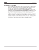
9000X AF Drives August 2010 Pump and Fan Control Application Control I/O Table 7-1: Pump and Fan Control Application Default I/O Configuration and Connection Example (with 2-wire transmitter) Terminal Reference potentiometer OPTA1 1 – 10 kW 1 +10Vref 2 AI1+ 2-wire transmitter 3 AI1+ Actual value 4 AI2+ 5 AI2+ - (0)4 … 20 mA 6 +24V 7 GND 8 DIN1 FAULT 9 DIN2 10 DIN3 11 12 13 14 CMA +24V GND DIN4 15 DIN5 16 DIN6 17 18 19 CMB AO1+ AO1(GND) DO1 20 OPTA2 21 22 23 220V AC 24 25 26 Signal Descript
9000X AF Drives August 2010 Pump and Fan Control Application 230V AC 22 24V DC RO1 12 SPX9000 OPTA2 25 RO2 9 DIN2 23 DIN3 10 26 Autom. 0 Line S1 Autom. 0 Line S2 K2 K1 K2 K2 K1.1 K1 K1 K1.1 M1/SPX9000 M1/Line K2.1 K2 M2/SPX9000 K2 K2.1 M2/Line Figure 7-1: 2-Pump Autochange System Principal Control Diagram MN04004001E For more information visit: www.eaton.
9000X AF Drives August 2010 Pump and Fan Control Application 230V AC SPX9000 OPTA1 24V DC 12 22 SPX9000 OPTA1 DIN3 10 9 DIN2 25 SPX9000 OPTB5 23 A O Line K2 K1.1 K1 29 A O Line K3 A O Line S3 K3 K1 K1 K3 K1 K1 K1.1 K2 K1 K2 K2 K2.1 K2 M1/SPX9000 M1/Line 28 SPX9000 OPTB5 S2 K2 14 26 S1 K3 SPX9000 OPTA1 DIN4 K2.1 M2/SPX9000 M2/Line K3 K3.1 K3 K3.1 M1/SPX9000 M3/Line Figure 7-2: 3-Pump Autochange System Principal Control Diagram 7-4 For more information visit: www.
9000X AF Drives August 2010 Pump and Fan Control Application Short Description of Function and Essential Parameters Automatic Changing Between Drives (Autochange, P1.9.24) The Autochange function allows the starting and stopping order of drives controlled by the pump and fan automatics to be changed at desired intervals. The drive controlled by frequency converter can also be included in the automatic changing and locking sequence (par. 1.9.25).
9000X AF Drives August 2010 Pump and Fan Control Application Parameters 1.9.27 — Maximum Number of Auxiliary Drives and 1.9.28 — Autochange Frequency Limit These parameters define the level below which the capacity used must remain so that the autochange can take place. This level is defined as follows: ● If the number of running auxiliary drives is smaller than the value of parameter 1.9.27 the autochange function can take place.
9000X AF Drives August 2010 Pump and Fan Control Application Examples Pump and fan automatics with interlocks and no autochange Situation: One controlled drive and three auxiliary drives. Parameter settings: 1.9.1 = 3, 1.9.25 = 0 Interlock feedback signals used, autochange not used. Parameter settings: 1.9.23 = 1, 1.9.24 = 0 The interlock feedback signals come from the digital inputs selected with parameters 1.2.6.18 to 1.2.6.21. The Auxiliary drive 1 control (par. 1.3.1.
9000X AF Drives August 2010 Pump and Fan Control Application Pump and fan automatics with interlocks and autochange The above is also applicable if the autochange function is used. In addition to the changed and updated start order, also the change order of main drives depends on parameter 1.9.23. On Off On Interlock 3 Off On Interlock 2 Off On Interlock 1 Off Interlock 4 Interlocks Relay Control 5 7 On Off On Off On Off On Off Aux. 3 Running Aux. 2 Running Aux. 1 Running Main Drive Running Max.
9000X AF Drives August 2010 Pump and Fan Control Application PE L1 L2 L3 F3 Q1 F1 L1 L2 L3 SVX9000 F2 1.1 2.1 K K U VW 1 2 K K M1 U VW PE M M2 3 U VW PE M 3 Figure 7-4: Example of 2-Pump Autochange, Main Diagram PE L1 L2 L3 F3 Q1 F1 F2 F2 L1 L2 L3 SVX9000 UVW 1.1 2.1 K 3.1 K 1 K 2 K 3 K M1 U V W M 3 K PE M2 U V W M 3 PE M2 U V W PE M 3 Figure 7-5: Example of 3-Pump Autochange, Main Diagram MN04004001E For more information visit: www.eaton.
9000X AF Drives August 2010 Pump and Fan Control Application Parameter Lists On the next pages you will find the lists of parameters within the respective parameter groups. The parameter descriptions are given in Chapter 8. Column explanations: Code = Parameter Min. Max.
9000X AF Drives August 2010 Pump and Fan Control Application Table 7-2: Monitoring Values (Continued) Code Parameter Unit ID Description V1.17 Analog input 4 V/mA 28 AI4 input value V1.18 PID Reference % 20 In % of the max. frequency V1.19 PID Actual value % 21 In % of the max actual value V1.20 PID Error value % 22 In % of the max error value V1.21 PID Output % 23 In % of the max output value V1.22 Running auxiliary drives 30 Number of running auxiliary drives V1.
9000X AF Drives August 2010 Pump and Fan Control Application Basic Parameters — G1.1 (Continued) Code Parameter Min. Max. P1.1.13 Local control reference 0 7 P1.1.14 Remote control reference 0 P1.1.15 PID controller reference signal (Place A) P1.1.16 PID controller gain P1.1.17 PID controller I-time 0.00 320.00 s 1.00 119 P1.1.18 PID controller Dtime 0.00 10.00 s 0.00 132 P1.1.19 Sleep frequency P1.1.1 P1.1.2 Hz 10.00 1016 P1.1.
9000X AF Drives August 2010 Pump and Fan Control Application Input Signals Basic Settings (Control Keypad: Menu M1 ➔ G1.2.1) Table 7-4: Input Signals, Basic Settings — G1.2.1 Code Parameter Min. Max. ID Note PID Reference 2 0 7 7 371 0 = AI1 1 = AI2 2 = AI3 3 = AI4 4 = PID reference 1 from keypad 5 = Fieldbus reference (FBProcessDataIN3) 6 = Motor potentiometer 7 = PID reference 2 from keypad P1.2.1.2 PID error value inversion 0 1 0 340 0 = No inversion 1 = Inversion P1.2.1.
9000X AF Drives August 2010 Pump and Fan Control Application Table 7-4: Input Signals, Basic Settings — G1.2.1 (Continued) Code Parameter Min. Max. P1.2.1.13 Motor 0 potentiometer frequency reference memory reset 2 P1.2.1.14 Motor potentiometer PID reference memory reset 0 P1.2.1.15 B reference scale, minimum 0.0 P1.2.1.16 B reference scale, maximum P1.2.1.15 320.
9000X AF Drives August 2010 Pump and Fan Control Application Analog Input 3 (Control Keypad: Menu M1 ➔ G1.2.4) Table 7-7: Input Signals, Analog Input 3 — G1.2.4 Code Parameter Min. Max. Unit Default P1.2.4.1 AI3 signal selection AnIN:0.1 AnIN:E.10 P1.2.4.2 AI3 filter time 0.00 10.00 P1.2.4.3 AI3 signal range 0 2 P1.2.4.4 AI3 custom minimum setting -100.00 100.00 P1.2.4.5 AI3 custom maximum setting -100.00 100.00 P1.2.4.6 AI3 inversion 0 1 Cust ID Note AnIN:0.1 141 0.
9000X AF Drives August 2010 Pump and Fan Control Application Table 7-9: Input Signals. Digital Inputs — G1.2.6 (Continued) Code Parameter Min. ID Note P1.2.6.8 Control from I/O terminal (Force Remote) DigIN:01 DigIn:E.10 DigIN:0.1 409 Force control place to Remote P1.2.6.9 Reverse DigIN:01 DigIn:E.10 DigIN:0.1 412 Direction forward (oc) Direction reverse (cc) P1.2.6.10 Jogging speed DigIN:01 DigIn:E.10 DigIN:A.5 413 Jogging speed selected for frequency reference (cc) P1.2.
9000X AF Drives August 2010 Pump and Fan Control Application Output Signals Digital Output Signals (Control Keypad: Menu M1 ➔ G1.3.1) Table 7-10: Output Signals, Digital Outputs — G1.3.1 Code Parameter Min. Max. Unit Default Cust ID P1.3.1.1 Ready DigOUT:0.1 DigOUT:E.10 DigOUT:0.1 432 P1.3.1.2 Run DigOUT:0.1 DigOUT:E.10 DigOUT:0.1 433 P1.3.1.3 Fault DigOUT:0.1 DigOUT:E.10 DigOUT:A.1 434 P1.3.1.4 Inverted fault DigOUT:0.1 DigOUT:E.10 DigOUT:0.1 435 P1.3.1.
9000X AF Drives August 2010 Pump and Fan Control Application Table 7-10: Output Signals, Digital Outputs — G1.3.1 (Continued) Code Parameter Min. Max. Unit Default Cust ID Note P1.3.1.24 Fieldbus digital DigOUT:0.1 DigOUT:E.10 input 1 DigOUT:0.1 455 P1.3.1.25 Fieldbus digital DigOUT:0.1 DigOUT:E.10 input 2 DigOUT:0.1 456 P1.3.1.26 Fieldbus digital DigOUT:0.1 DigOUT:E.10 input 3 DigOUT:0.1 457 P1.3.1.27 Autochange 1/ Aux 1 control DigOUT:0.1 DigOUT:E.10 DigOUT:B.1 458 P1.3.1.
9000X AF Drives August 2010 Pump and Fan Control Application Table 7-11: Output Signals, Limit Settings — G1.3.2 (Continued) Code Parameter Min. Max. Unit Default P1.3.2.12 FC temperature supervised value -10 75 ∞C P1.3.2.13 Supervised analog input 0 P1.3.2.14 Analog input supervision limit P1.3.2.15 Analog input supervised value Cust ID Note 40 355 1 0 372 0 = AI1 1 = AI2 0 2 0 373 0 = No limit 1 = Low limit supervision 2 = High limit supervision 0.00 100.00 0.
9000X AF Drives August 2010 Pump and Fan Control Application Analog Output 2 (Control Keypad: Menu M1 ➔ G1.3.4) Table 7-13: Output Signals, Analog Output 2 — G1.3.4 Code Parameter Min. Max. Unit Default P1.3.4.1 Analog output 2 signal selection AnOUT:01 AnOUT:E.10 AnOUT:0.1 471 P1.3.4.2 Analog output 2 function 0 14 0 472 See P1.3.3.2 P1.3.4.3 Analog output 2 filter time 0.00 10.00 1.00 473 0.00 = No filtering P1.3.4.
9000X AF Drives August 2010 Pump and Fan Control Application Drive Control Parameters (Control Keypad: Menu M1 ➔ G1.4) Table 7-15: Drive Control Parameters — G1.4 Code Parameter Min. Max. Unit Default P1.4.1 Ramp 1 shape 0.0 10.0 s P1.4.2 Ramp 2 shape 0.0 10.0 P1.4.3 Acceleration time 2 0.1 P1.4.4 Deceleration time 2 0.1 Brake chopper 0 P1.4.6 Start mode P1.4.7 Stop mode P1.4.5 Cust ID Note 0.0 500 0.00 = Linear >0.00 = S-curve ramp time s 0.0 501 0.00 = Linear >0.
9000X AF Drives August 2010 Pump and Fan Control Application Skip Frequencies (Control Keypad: Menu M1 ➔ G1.5) Table 7-16: Skip Frequencies— G1.5 Code Parameter Min. Max. Unit Default Cust ID Note P1.5.1 Skip frequency range 1 low limit 0.0 P1.5.2 Hz 0.00 509 P1.5.2 Skip frequency range 1 high limit P1.5.1 320.00 Hz 0.00 510 P1.5.3 Skip frequency range 2 low limit 0.00 P1.5.4 Hz 0.00 511 P1.5.4 Skip frequency range 2 high limit P1.5.3 320.00 Hz 0.00 512 P1.5.
9000X AF Drives August 2010 Pump and Fan Control Application Protections (Control keypad: Menu M1 ➔ G1.7) Table 7-18: Protections — G1.7 Code Parameter Min. Max. P1.7.1 Response to reference fault 0 5 P1.7.2 4mA reference fault 0.00 frequency P1.1.2 P1.7.3 Response to external fault 0 P1.7.4 Input phase supervision P1.7.5 ID Note 0 700 0 = No response 1 = Warning 2 = Warning+Previous Freq. 3 = Warning+Preset Freq P1.7.2 4 = Fault, stop acc. to P1.4.7 5 = Fault, stop by coasting 0.
9000X AF Drives August 2010 Pump and Fan Control Application Table 7-18: Protections — G1.7 (Continued) Code Parameter Min. Max. P1.7.22 Response to fieldbus fault 0 3 P1.7.23 Response to slot fault 0 P1.7.24 P1.7.25 ID Note 2 733 See P1.7.3 3 2 734 See P1.7.3 No. of PT100 inputs 0 3 0 739 Response to PT100 fault 1 1 740 P1.7.26 PT100 warning limit -30.0 120.0 741 P1.7.27 PT100 fault limit P1.7.28 FB MCW Bit 15 0 Unit Default 200.0 °C -30.0 200.
9000X AF Drives August 2010 Pump and Fan Control Application Pump and Fan Control Parameters (Control Keypad: Menu M1 ➔ G1.9) Table 7-20: Pump and Fan Control Parameters — G1.9 Code Parameter Min. Max. P1.9.1 Number of auxiliary 0 drives 4 P1.9.2 Start frequency. auxiliary drive 1 P1.9.3 320.00 P1.9.3 Stop frequency. auxiliary drive 1 P1.1.1 P1.9.4 Start frequency. auxiliary drive 2 P1.9.5 Unit Default Cust ID Note 0 1001 Hz 61.00 1002 P1.9.2 Hz 10.00 1003 P1.9.5 320.
9000X AF Drives August 2010 Pump and Fan Control Application Table 7-20: Pump and Fan Control Parameters — G1.9 (Continued) Code Parameter P1.9.22 Min. Max. Unit Default Frequency increase 0.0 delay 300.0 s P1.9.23 Interlock selection 0 P1.9.24 Autochange P1.9.25 ID Note 0.0 1026 0.0 = No delay 300.0 = No frequency drop 2 0 1032 0 = Interlocks not used 1 = Set new interlock last; update order after value of P1.9.
9000X AF Drives August 2010 Pump and Fan Control Application Menus — M3 to M6 Menus M3 to M6 provide information on the Active Faults, Fault History, System Menu settings and the Expander Board setup. These menu items are explained in detail in Chapter 5 of the 9000X AF Drives User Manual. Monitoring Menu — M7 The monitored items are the actual values of parameters and signals as well as the status and measurements of other elements. Monitored items cannot be edited.
9000X AF Drives August 2010 7-28 For more information visit: www.eaton.
9000X AF Drives August 2010 Chapter 8 — Description of Parameters Introduction On the following pages you will find the parameter descriptions arranged according to the individual ID number of the parameter. A parameter ID number with a footnote (e.g. 418 Motor potentiometer UP) indicates that the TTF programming method shall be applied to this parameter (see Page 6-3). Some parameter names are followed by a number code indicating the “All-in-One” applications in which the parameter is included.
9000X AF Drives August 2010 Description of Parameters 107 Current limit (P1.5, P1.1.5) This parameter determines the maximum motor current from the frequency converter. The parameter value range differs from size to size. 108 V/Hz ratio selection Linear: 0 Squared: 1 234567 (P1.6.3) The voltage of the motor changes linearly with the frequency in the constant flux area from 0 Hz to the field weakening point where the nominal voltage is supplied to the motor.
9000X AF Drives August 2010 Description of Parameters U[V] Un ID603 Default: Nominal Voltage of the Motor ID605 (Default 10%) Field Weakening Point Default: Nominal Frequency of the Motor ID606 (Default 1.3%) ID604 (Default 5 Hz) f[Hz] ID602 Figure 8-2: Programmable V/Hz Curve Linear with flux optimization: 3 The frequency converter starts to search for the minimum motor current in order to save energy, lower the disturbance level and the noise.
9000X AF Drives August 2010 Description of Parameters 8-4 110 Nominal voltage of the motor (P1.6, P1.1.6) Find this value Vn on the rating plate of the motor. This parameter sets the voltage at the field weakening point (ID603) to 100% * VnMotor. 111 Nominal frequency of the motor (P1.7, P1.1.7) Find this value fn on the rating plate of the motor. This parameter sets the field weakening point (ID602) to the same value. 112 Nominal speed of the motor (P1.8, P1.1.
9000X AF Drives August 2010 Description of Parameters Table 8-2: Preset Speeds 3 to 7 132 Speed Multi-step speed select 1 (DIN4) Multi-step speed select 2 (DIN5) Multi-step speed select 3 (DIN6) Multi-step speed select 4 (DIN3) Basic speed 0 0 0 0 P1.1.17 (3) 1 1 0 0 P1.1.18 (4) 0 0 1 0 P1.1.19 (5) 1 0 1 0 P1.1.20 (6) 0 1 1 0 P1.1.21 (7) 1 1 1 0 PID controller D-time 57 (P1.1.14) ID132 defines the derivative time of the PID controller. If this parameter is set to 1.
9000X AF Drives August 2010 Description of Parameters Hz PID Output Error Value 10% I-Part = 5 Hz/s 10% I-Part = 5 Hz/s I-Part = 5 Hz/s 10% I-Part = 5 Hz/s 10% Error = 10% I-Part = 5 Hz/s t 1s Figure 8-3: PID Controller Function as I-Controller Example 2: Given values: P1.1.12, P = 100% P1.1.13, I-time = 1.00 s P1.1.14, D-time = 1.00 s Min freq. = 0 Hz Error value (setpoint – process value) = ±10% Max freq.
9000X AF Drives August 2010 Description of Parameters Example 3: Given values: P1.1.12, P = 100% P1.1.13, I-time = 0.00 s P1.1.14, D-time = 1.00 s Min freq. = 0 Hz Error value (setpoint – process value) = ±10%/s Max freq. = 60 Hz As the error value increases, the PID output also increases according to the set values (D-time = 1.00s) Hz PID Output Error Value D-part = 10% = 5.00 Hz /s pa % 10 D- s %/ -10 art p D- rt D-part = -10% = -5.00 Hz P-part = 100% *PID error = 5.000 Hz/s 10% t 1.
9000X AF Drives August 2010 Description of Parameters 141 AI3 signal selection 567 (P1.2.38, P1.2.4.1) Connect the AI3 signal to the analog input of your choice with this parameter. For more information, see Page 6-3, “Terminal to Function” (TTF) programming principle. 142 AI3 signal filter time 567 (P1.2.41, P1.2.4.2) When this parameter is given a value greater than 0, the function that filters out disturbances from the incoming analog signal is activated.
9000X AF Drives August 2010 Description of Parameters 164 Motor control mode 1/2 6 (P1.2.7.22) Contact is open = Motor control mode 1 is selected. Contact is closed = Motor control mode 2 is selected. See ID600 and ID521. 165 AI1 joystick offset 6 (P1.2.2.11) Define the frequency zero point as follows: With this parameter being displayed, place the potentiometer at the assumed zero point and press ENTER on the keypad. Note: This will not change the reference scaling.
9000X AF Drives August 2010 Description of Parameters Table 8-6: Selections for ID173, ID174 and ID175 Application Select 2–4 5 6 7 0 Analog voltage ref. Analog voltage ref. Analog voltage ref. Analog voltage ref. Terminals 2 – 3 Terminals 2 – 3 Terminals 2 – 3 Terminals 2 – 3 1 Analog current ref. Analog current ref. Analog current ref. Analog current ref.
9000X AF Drives August 2010 Description of Parameters FWD Output Frequency Stop Function (ID506) = Coasting t REV DIN1 DIN2 1 2 3 Figure 8-6: Start Forward/Start Reverse 1 The first selected direction has the highest priority. When the DIN1 contact opens the direction of rotation starts to change. If Start forward (DIN1) and Start reverse (DIN2) signals are active simultaneously the Start forward signal (DIN1) has priority.
9000X AF Drives August 2010 Description of Parameters 2 DIN1: closed contact = start — open contact = stop DIN2: closed contact = start enabled — open contact = start disabled and drive stopped if running, see Figure 8-8. 3 3-wire connection (pulse control): DIN1: closed contact = start pulse DIN2: open contact = stop pulse (DIN3 can be programmed for reverse command), see Figure 8-8.
9000X AF Drives August 2010 Description of Parameters The selections including the text “Rising edge required to start” shall be used to exclude the possibility of an unintentional start when, for example, power is connected, re-connected after a power failure, after a fault reset, after the drive is stopped by Run Enable (Run Enable = False) or when the control place is changed. The Start/Stop contact must be opened before the motor can be started.
9000X AF Drives August 2010 Description of Parameters 301 DIN3 function 0 1 2 3 12345 (P1.17, P1.2.
9000X AF Drives August 2010 Description of Parameters Output Frequency ID515 t t DIN2 DIN2 RUN STOP RUN STOP a) DIN3 as DC-brake command input and stop-mode = Ramp b) DIN3 as DC-brake command input and stop-mode = Coasting Figure 8-9: DIN3 as DC-Brake Command Input a) Stop mode = ramp, b) Stop mode = coasting 302 Reference offset for current input 12 (P1.15, P1.2.3) 0 No offset: 0 – 20 mA 1 Offset: 4 mA (“living zero”) provides supervision of zero level signal.
9000X AF Drives August 2010 Description of Parameters 305 Reference inversion 2 (P1.2.6) Inverts reference signal: Max. ref. signal = Min. set freq. Min. ref. signal = Max. set freq. 0 No inversion 1 Reference inverted Output Frequency Max. Freq. ID102 ID304 ID303 Analog Input Min. Freq. ID101 0 Max. Figure 8-11: Reference Inversion 306 Reference filter time 2 (P1.2.7) Filters out disturbances from the incoming analog Vin signal. A long filtering time makes regulation response slower.
9000X AF Drives August 2010 Description of Parameters 308 Analog output filter time 234567 (P1.3.3, P1.3.5.3, P1.3.3.3) Defines the filtering time for the analog output signal. Setting this parameter value to 0.00 will deactivate filtering. % Unfiltered Signal 100% Filtered Signal 63% t [s] ID308 Figure 8-13: Analog Output Filtering 309 Analog output inversion 234567 (P1.3.4, P1.3.5.4, P1.3.3.
9000X AF Drives August 2010 Description of Parameters 311 Analog output scale 234567 (P1.3.6, P1.3.5.6, P1.3.3.6) Scaling factor for analog output. Table 8-7: Analog Output Scaling Signal Max. value of the signal Output frequency Max frequency (ID102) Freq. Reference Max frequency (ID102) Motor speed Motor nom. speed 1xnmMotor Output current Motor nom. current 1xInMotor Motor torque Motor nom. torque 1xTnMotor Motor power Motor nom.
9000X AF Drives August 2010 Description of Parameters Table 8-8: Output Signals Via DO1 and Output Relays RO1 and RO2 Setting value Signal content 0 = Not used Out of operation Digital output DO1 sinks current and programmable relay (RO1, RO2) is activated when: 1 = Ready The frequency converter is ready to operate 2 = Run The frequency converter is operating (motor is running) 3 = Fault A fault trip has occurred 4 = Fault inverted A fault trip not occurred 5 = Overheat warning The heat-sink t
9000X AF Drives August 2010 Description of Parameters Table 8-8: Output Signals Via DO1 and Output Relays RO1 and RO2, (Continued) Setting value Signal content 22 = Thermistor fault or warning (Applications 3456) The thermistor input of option board indicates overtemperature. Fault or warning depending on ID732. 23 = Fieldbus input data (Application 5) 23 = On/Off control (Application 6) Fieldbus input data (FBFixedControlWord) to DO/RO.
9000X AF Drives August 2010 Description of Parameters 319 DIN2 function 5 (P1.2.1) This parameter has 14 selections. If digital input DIN2 is not used, set this value to 0.
9000X AF Drives August 2010 Description of Parameters Output Frequency Output Frequency ID515 t t DIN2 DIN2 RUN STOP RUN STOP Figure 8-17: DC Braking Command (Selection 12) Selected for DIN2 Left: Stop mode = ramp, Right: Stop mode = coasting 320 AI1 signal range 34567 (P1.2.4, P1.2.16, P1.2.2.
9000X AF Drives August 2010 Description of Parameters 323 AI1 signal inversion 3457 (P1.2.7, P1.2.19, P1.2.2.6) If this parameter = 0 no inversion of analog Vin signal takes place. Note: In Application 3, AI1 is place B frequency reference if parameter ID131 = 0 (default). Output Frequency ID303 ID320 = 0 AI1 = 0 – 100% ID320 = 1 AI1 = Custom ID304 0 ID321 ID322 AI1 (Term. 2) 100% Figure 8-18: AI1 No Signal Inversion If this parameter = 1 inversion of analog signal takes place. max.
9000X AF Drives August 2010 Description of Parameters 324 AI1 signal filter time 34567 (P1.2.8, P1.2.20, P1.2.2.2) When this parameter is given a value greater than 0, the function that filters out disturbances from the incoming analog signal is activated. A long filtering time makes the regulation response slower. See Figure 8-20. % Unfiltered Signal 100% Filtered Signal 63% t [s] ID308 Figure 8-20: AI1 Signal Filtering 325 Analog input AI2 signal range 34567 (P1.2.10, P1.2.22, P1.2.3.
9000X AF Drives August 2010 Description of Parameters 326 327 Analog input AI2 custom setting min. Analog input AI2 custom setting max. 34567 (P1.2.11, P1.2.23, P1.2.3.4) 34567 (P1.2.12, P1.2.24, P1.2.3.5) These parameters set AI2 for any input signal span within 0 – 100%. 328 Analog input AI2 inversion 3457 (P1.2.13, P1.2.25, P1.2.3.6) See ID323. Note: In Application 3, AI2 is the place A frequency reference, if ID117 = 1 (default) 329 Analog input AI2 (Iin) filter time 34567 (P1.2.14, P1.2.
9000X AF Drives August 2010 Description of Parameters 333 PID controller actual value selection 57 (P1.2.8, P1.2.1.8) This parameter selects the PID controller actual value.
9000X AF Drives August 2010 Description of Parameters Scaled Input Signal [%] Scaled Input Signal [%] 100 100 ID336 = 30% ID337 = 80% 76.5 (15.3 mA) ID338 = -30% ID339 = 140% 17.7 (3.5 mA) 30 0 0 0 4 3.3 6.0 8.8 80 Analog 100 Input [%] 8.0 16.0 16.8 -30 10.0V 20.0 mA 20.0 mA 100 0 0 0 4 Analog 140 Input [%] 10.0V 20.0 mA 20.0 mA Figure 8-22: Examples of Actual Value Signal Scaling 340 PID error value inversion 57 (P1.2.32, P1.2.1.
9000X AF Drives August 2010 Description of Parameters 345 Reference scaling maximum value, place B 57 (P1.2.36, P1.2.1.19) You can choose a scaling range for the frequency reference from control place B between the Minimum and Maximum frequency. If no scaling is desired set the parameter value to 0.0. In Figure 8-23, input AI1 with signal range 0 – 100% is selected for Place B reference. Output Frequency Output Frequency Max. Frequency ID102 Max. Frequency ID102 ID345 Analog Input [V] Min.
9000X AF Drives August 2010 Description of Parameters 348 Torque limit, supervision 34567 (P1.3.14, P1.3.4.5, P1.3.2.5) function 0 No supervision 1 Low limit supervision 2 High limit supervision 3 Brake-off control (Application 6 only, see Page A-1.
9000X AF Drives August 2010 Description of Parameters 352 353 External brake-off delay External brake-on delay 34567 34567 (P1.3.18, P1.3.4.9, P1.3.2.9) (P1.3.19, P1.3.4.10, P1.3.2.10) The function of the external brake can be timed to the start and stop control signals with these parameters. See Figure 8-24 and Page A-1.
9000X AF Drives August 2010 Description of Parameters 357 358 On/Off control low limit On/Off control high limit 6 6 (P1.3.4.14) (P1.3.4.15) These parameters set the low and high limits of the signal selected with ID356. See Figure 8-25. Analog Input (Selected with ID356) ID358 ID357 Time RO1 1 0 In this example the programming of ID463 = B.1. Figure 8-25: An Example of On/Off-Control 359 360 PID controller minimum limit PID controller maximum limit 5 5 (P1.2.30) (P1.2.
9000X AF Drives August 2010 Description of Parameters 362 Free analog input, function 34 (P1.2.21, P1.2.18) This parameter is used for selecting a function for the free analog input signal: 0 Function is not in use 1 Reduces motor current limit (ID107) This signal will adjust the maximum motor current between 0 and maximum limit set with ID107. See Figure 8-26. Torque Limit 100% ID107 Analog Input 0V 0 mA 4 mA Custom Signal Range 10 V 20 mA 20 mA Custom Figure 8-26: Scaling of Max.
9000X AF Drives August 2010 Description of Parameters 3 Reduces acceleration and deceleration times Acceleration and deceleration times can be reduced with the free analog input signal according to the following formulas: Reduced time = set acc./decel. time (ID103, ID104; ID502, ID503) divided by the factor R in Figure 8-28.
9000X AF Drives August 2010 Description of Parameters 363 Start/Stop logic selection, 3 (P1.2.15) place B 0 DIN4: closed contact = start forward DIN5: closed contact = start reverse FWD Output Frequency Stop Function (ID506) = Coasting t REV DIN4 DIN5 1 2 3 Figure 8-30: Place B Start Forward/Start Reverse 1 FWD The first selected direction has the highest priority. When the DIN4 contact opens the direction of rotation starts to change.
9000X AF Drives August 2010 Description of Parameters 2 DIN4: closed contact = start — open contact = stop DIN5: closed contact = start enabled — open contact = start disabled and drive stopped if running 3-wire connection (pulse control): DIN4: closed contact = start pulse DIN5: open contact = stop pulse (DIN3 can be programmed for reverse command) See Figure 8-32. 3 Output Frequency Stop Function (ID506) = Coasting If Start and Stop pulses are simultaneous the Stop pulse overrides the Start pulse.
9000X AF Drives August 2010 Description of Parameters 367 Motor potentiometer memory 3567 (P1.2.23, P1.2.28, P1.2.1.3, P1.2.1.16) reset (Frequency reference) 0 No reset 1 Memory reset in stop and power down 2 Memory reset in power down 370 Motor potentiometer memory 57 (P1.2.29, P1.2.1.17) reset (PID reference) 0 No reset 1 Memory reset in stop and power down 2 Memory reset in power down 371 PID reference 2 (Place A additional reference) 7 (P1.2.1.
9000X AF Drives August 2010 Description of Parameters 374 Analog input supervised value 7 (P1.3.2.15) The value of the selected analog input to be supervised by ID373. 375 Analog output offset 67 (P1.3.5.7, P1.3.3.7) Add -100.0 to 100.0% to the analog output. 376 PID sum point reference (Place A direct reference) 5 (P1.2.4) Defines which reference source is added to PID controller output if PID controller is used.
9000X AF Drives August 2010 Description of Parameters 234567 377 AI1 signal selection (P1.2.8, P1.2.3, P1.2.15, P1.2.2.1) Connect the AI1 signal to the analog input of your choice with this parameter. For more information about the TTF programming method, see Page 6-3. 384 6 AI1 joystick hysteresis (P1.2.2.8) This parameter defines the joystick hysteresis between 0 and 20%.
9000X AF Drives August 2010 Description of Parameters 385 6 AI1 sleep limit (P1.2.2.9) The frequency converter is automatically stopped if the AI signal level falls below the Sleep limit defined with this parameter. See Figure 8-35. Frequency Reference Hz Reference Scaling Max ID304 = 70 Hz FORWARD 50% REVERSE 50% A B From Reverse to Forward Max Freq. ID102 = 50 Hz START STOP Min Freq. ID101 = Ref.
9000X AF Drives August 2010 Description of Parameters Frequency reference Hz Reference Scaling Max P2.2.2.7 = 70 Hz REVERSE 50% FORWARD 50% A B From Reverse to Forward Max Freq. P2.1.2 = 50 Hz From Forward to Reverse Min Freq. P2.1.1 = Ref. Scaling Min P2.2.2.6 = 0 Hz Analog Input (V/mA) (0 – 10V/20 mA) Par. 2.2.2.4 = 20% Joystick Hysteresis, P2.2.2.8 = 20% Par. 2.2.2.5 = 90% Figure 8-36: Joystick Hysteresis with Minimum Frequency at 35 Hz 386 6 AI1 sleep delay (P1.2.2.
9000X AF Drives August 2010 Description of Parameters AI2 reference scaling, minimum value AI2 reference scaling, maximum value See ID303 and ID304. 6 (P1.2.3.6) 6 (P1.2.3.7) 395 AI2 joystick hysteresis See ID384. 6 (P1.2.3.8) 396 AI2 sleep limit See ID385. 6 (P1.2.3.9) 397 AI2 sleep delay See ID386. 6 (P1.2.3.10) 399 Scaling of current limit 6 (P1.2.6.1) 0 Not used 1 AI1 2 AI2 3 AI3 4 AI4 5 Fieldbus (FBProcessDataIN2) This signal will adjust the maximum motor current between 0 and max.
9000X AF Drives August 2010 Description of Parameters 401 Reducing of acceleration and 6 (P1.2.6.3) deceleration times See ID399. Acceleration and deceleration times can be reduced with the free analog input signal according to the following formulas: Reduced time = set acc./deceler. time (ID103, ID104; ID502, ID503) divided by the factor R from Figure 8-38.
9000X AF Drives August 2010 Description of Parameters 403 Start signal 1 6 (P1.2.7.1) Signal selection 1 for the start/stop logic. Default programming A.1. 404 Start signal 2 6 (P1.2.7.2) Signal selection 2 for the start/stop logic. Default programming A.2. 405 External fault (close) 67 (P1.2.7.11, P1.2.6.4) Contact closed: Fault is displayed and motor stopped 406 External fault (open) 67 (P1.2.7.12, P1.2.6.5) Contact open: Fault is displayed and motor stopped 407 Run enable 67 (P1.
9000X AF Drives August 2010 Description of Parameters 414 Fault reset 67 (P1.2.7.10, P1.2.6.13) Contact closed: All faults are reset. 415 Acceleration/Deceleration prohibited 67 (P1.2.7.14, P1.2.6.14) Contact closed: No acceleration or deceleration possible until the contact is opened. 416 DC-braking 67 (P1.2.7.15, P1.2.6.15) Contact closed: In STOP mode, the DC braking operates until the contact is opened. 417 Motor potentiometer DOWN 67 (P1.2.7.8, P1.2.6.
9000X AF Drives August 2010 Description of Parameters 426 Autochange 1 interlock 7 (P1.2.6.18) Contact closed: Interlock of autochange drive 1 or auxiliary drive 1 activated. Default programming: A.2. 427 Autochange 2 interlock 7 (P1.2.6.19) Contact closed: Interlock of autochange drive 2 or auxiliary drive 2 activated. Default programming: A.3. 428 Autochange 3 interlock 7 (P1.2.6.20) Contact closed: Interlock of autochange drive 3 or auxiliary drive 3 activated.
9000X AF Drives August 2010 Description of Parameters 437 External fault or warning 67 (P1.3.3.6, P1.3.1.6) Fault or warning depending on ID701. 438 Reference fault or warning 67 (P1.3.3.7, P1.3.1.7) Fault or warning depending on ID700. 439 Overtemperature warning 67 (P1.3.3.8, P1.3.1.8) The heatsink temperature exceeds +70°C. 440 Reverse 67 (P1.3.3.9, P1.3.1.9) The Reverse command has been selected. 441 Unrequested direction 67 (P1.3.3.10, P1.3.1.
9000X AF Drives August 2010 Description of Parameters 449 Reference limit supervision 67 (P1.3.3.18, P1.3.1.18) Active reference is beyond the set supervision low limit/high limit (see ID350 and ID351). 450 Temperature limit supervision 67 (P1.3.3.19, P1.3.1.19) The frequency converter heatsink temperature is beyond the set supervision limits (see ID354 and ID355). 451 Torque limit supervision 67 (P1.3.3.20, P1.3.1.
9000X AF Drives August 2010 Description of Parameters 461 Autochange 4/Auxiliary drive 4 7 control (P1.3.1.30) Control signal for autochange/auxiliary drive 4. If three (or more) auxiliary drives are used, we recommend the use of relay outputs, to connect drives 3 and 4. Since the OPTA2 board only has two relay outputs it is advisable to purchase an I/O expander board with extra relay outputs (e.g. OPTB5). 462 Autochange 5 control 7 (P1.3.1.31) Control signal for autochange drive 5.
9000X AF Drives August 2010 Description of Parameters 481 Analog output 3 inversion 67 (P1.3.7.4, P1.3.5.4) 67 (P1.3.7.5, P1.3.5.5) 67 (P1.3.7.6, P1.3.5.6) 67 (P1.3.7.7, P1.3.5.7) 6 (P1.2.6.5) 6 (P1.3.1.1) See ID309. 482 Analog output 3 minimum See ID310. 483 Analog output 3 scaling See ID311. 484 Analog output 3 offset See ID375. 485 Torque limit See ID399 for the selections.
9000X AF Drives August 2010 Description of Parameters 492 Digital output 2 off-delay See ID488. 493 Adjust input 6 (P1.2.1.4) With this parameter you can select the signal, according to which the frequency reference to the motor is fine adjusted. 0 Not used 1 Analog input 1 2 Analog input 2 3 Analog input 3 4 Analog input 4 5 Signal from fieldbus (FBProcessDataIN) 494 495 Adjust minimum 6 (P1.2.1.5) Adjust maximum 6 (P1.2.1.6) These parameters define the minimum and maximum of adjusted signals.
9000X AF Drives August 2010 Description of Parameters 498 Start pulse memory 3 (P1.2.24) Giving a value to this parameter determines if the present RUN status is copied when the control place is changed from A to B or vice versa. 0 The RUN status is not copied 1 The RUN status is copied In order for this parameter to have effect, ID300 and ID363 must have been set the value 3. 500 501 Acceleration/Deceleration ramp 1 shape Acceleration/Deceleration ramp 2 shape 234567 (P1.4.1) 234567 (P1.4.
9000X AF Drives August 2010 Description of Parameters 504 Brake chopper 234567 (P1.4.5) 0 No brake chopper used 1 Brake chopper in use and tested when running. Can be tested also in READY state 2 External brake chopper (no testing) 3 Used and tested in READY state and when running 4 Used when running (no testing) When the frequency converter is decelerating the motor, the inertia of the motor and the load is fed into an external brake resistor.
9000X AF Drives August 2010 Description of Parameters 507 DC-braking current 234567 (P1.4.8) Defines the current injected into the motor during DC-braking. 508 DC-braking time at stop 234567 (P1.4.9) Determines if braking is ON or OFF and the braking time of the DC-brake when the motor is stopping. The function of the DC-brake depends on the stop function, ID506. 0.0 DC-brake is not used >0.0 DC-brake is in use and its function depends on the Stop function, (ID506).
9000X AF Drives August 2010 Description of Parameters Par. ID506 = 1; Stop function = Ramp: After the Stop command, the speed of the motor is reduced according to the set deceleration parameters, as fast as possible, to the speed defined with ID515, where the DC-braking starts. The braking time is defined with ID508. If high inertia exists, it is recommended to use an external braking resistor for faster deceleration. See Figure 8-44.
9000X AF Drives August 2010 Description of Parameters 509 510 511 512 513 514 Skip frequency area 1; Low limit Skip frequency area 1; High limit Skip frequency area 2; Low limit Skip frequency area 2; High limit Skip frequency area 3; Low limit Skip frequency area 3; High limit 234567 (P1.5.1) 234567 (P1.5.2) 34567 (P1.5.3) 34567 (P1.5.4) 34567 (P1.5.5) 34567 (P1.5.6) In some systems it may be necessary to avoid certain frequencies because of mechanical resonance problems.
9000X AF Drives August 2010 Description of Parameters 518 Acceleration/deceleration ramp 234567 speed scaling ratio between skip frequency limits (P1.5.3, P1.5.7) Defines the acceleration/deceleration time when the output frequency is between the selected skip frequency range limits (ID509 and ID510). The ramping speed (selected acceleration/deceleration time 1 or 2) is multiplied with this factor. E.g. value 0.1 makes the acceleration time 10 times shorter than outside the skip frequency range limits.
9000X AF Drives August 2010 Description of Parameters 521 Motor control mode 2 6 (P1.6.12) With this parameter you can set another motor control mode. The mode which is used is determined by ID164. For the available selections, see ID600. 600 Motor control mode 234567 (P1.6.1) SVX: 0 Frequency control: The I/O terminal and keypad references are frequency references and the frequency converter controls the output frequency (output frequency resolution = 0.
9000X AF Drives August 2010 Description of Parameters 603 Voltage at field weakening point 234567 (P1.6.5) Above the frequency at the field weakening point, the output voltage remains at the set maximum value. Below the frequency at the field weakening point, the output voltage depends on the setting of the V/Hz curve parameters. See ID109, ID108, ID604 and ID605.
9000X AF Drives August 2010 Description of Parameters 610 Torque limit control P-gain 6 (P1.10.2) This parameter defines the gain of the torque limit controller. 611 Torque limit control I-gain 6 (P1.10.3) This parameter determines the I-gain of the torque limit controller. 612 CL: Magnetizing current 234567 (P1.6.12.1, P1.6.15.1) Sets the motor magnetizing current (no-load current). See Page A-3. 613 CL: Speed control P-gain 234567 (P1.6.12.2, P1.6.15.
9000X AF Drives August 2010 Description of Parameters 620 CL: Load drooping 234567 (P1.6.12.4, P1.6.15.4) The drooping function enables speed drop as a function of load. This parameter sets that amount corresponding to the nominal torque of the motor. See Page A-3. 621 CL: Startup torque 234567 (P1.6.12.11, P1.6.15.11) Chooses the startup torque. Torque Memory is used in crane applications. Startup torque FWD/REV can be used in other applications to help the speed controller. See Page A-3.
9000X AF Drives August 2010 Description of Parameters 636 Minimum frequency for Open Loop torque control 6 (P1.10.8) Defines the frequency limit below which the frequency converter operates in the frequency control mode. Because of the nominal slip of the motor, the internal torque calculation is inaccurate at low speeds where it is recommended to use the frequency control mode. 637 Speed controller P gain, Open Loop 6 (P1.6.13) Defines the P gain for the speed controlled in Open Loop control mode.
9000X AF Drives August 2010 Description of Parameters 644 Torque speed limit 6 (P1.10.7) With this parameter the maximum frequency for the torque control can be selected. 0 Maximum frequency, ID102 1 Selected frequency reference 2 Preset speed 7, ID130 700 Response to the reference fault 234567 (P1.7.
9000X AF Drives August 2010 Description of Parameters 704 Motor thermal protection 234567 (P1.7.8) 0 No response 1 Warning 2 Fault, stop mode after fault according to ID506 3 Fault, stop mode after fault always by coasting If tripping is selected the drive will stop and activate the fault stage. Deactivating this protection, i.e. setting parameter to 0, will reset the thermal stage of the motor to 0%. See Page A-4. 705 Motor thermal protection: Motor ambient temp. factor 234567 (P1.7.
9000X AF Drives August 2010 Description of Parameters 707 Motor thermal protection: Time constant 234567 (P1.7.11) This time can be set between 1 and 200 minutes. This is the thermal time constant of the motor, the larger the motor, the longer the time constant. The time constant is the time within which the calculated thermal stage has reached 63% of its final value. The motor thermal time is specific to the motor design and it varies between different motor manufacturers.
9000X AF Drives August 2010 Description of Parameters 710 Stall current limit 234567 (P1.7.14) The current can be set to 0.1 – InMotor*2. For a stall stage to occur, the current must have exceeded this limit. See Figure 8-49. The software does not allow entering a greater value than InMotor*2. If ID113, nominal motor current is changed, this parameter is automatically restored to the default value (IL). See Page A-4.
9000X AF Drives August 2010 Description of Parameters 712 Stall frequency limit 234567 (P1.7.16) The frequency can be set between 1 – fmAx (ID102). For a stall state to occur, the output frequency must have remained below this limit. See Page A-4. 713 Underload protection 234567 (P1.7.17) 0 No response 1 Warning 2 Fault, stop mode after fault according to ID506 3 Fault, stop mode after fault always by coasting If tripping is set active the drive will stop and activate the fault stage.
9000X AF Drives August 2010 Description of Parameters 716 Underload time 234567 (P1.7.20) This time can be set between 2.0 and 600.0s. This is the maximum time allowed for an underload state to exist. An internal up/ down counter counts the accumulated underload time. If the underload counter value goes above this limit the protection will cause a trip according to ID713. If the drive is stopped the underload counter is reset to zero. See Figure 8-52 and Page A-5.
9000X AF Drives August 2010 Description of Parameters 718 Automatic restart: Trial time 234567 (P1.8.2) The Automatic restart function restarts the frequency converter when the faults selected with ID720 to ID725 have cleared and the waiting time has elapsed. Wait Time Par. ID717 Wait Time Par. ID717 Wait Time Par. ID717 Fault Trigger Motor Stop Signal Restart 1 Restart 2 Motor Start Signal Trial Time Par.
9000X AF Drives August 2010 Description of Parameters 720 Automatic restart: Number of tries after undervoltage fault trip 234567 (P1.8.4) This parameter determines how many automatic restarts can be made during the trial time set by ID718 after an undervoltage trip. 0 No automatic restart >0 Number of automatic restarts after undervoltage fault. The fault is reset and the drive is started automatically after the DC-link voltage has returned to the normal level.
9000X AF Drives August 2010 Description of Parameters 726 Automatic restart: Number of tries after motor temperature fault trip 234567 (P1.8.8) This parameter determines how many automatic restarts can be made during the trial time set by ID718. 0 No automatic restart after Motor temperature fault trip >0 Number of automatic restarts after the motor temperature has returned to its normal level 727 Response to undervoltage fault 234567 (P1.7.
9000X AF Drives August 2010 Description of Parameters 732 Response to thermistor fault 234567 (P1.7.21) 0 No response 1 Warning 2 Fault, stop mode after fault according to ID506 3 Fault, stop mode after fault always by coasting Setting the parameter to 0 will deactivate the protection. 733 Response to fieldbus fault 234567 (P1.7.22) This sets the response mode for the fieldbus fault when a fieldbus board is used. For more information, see the respective Fieldbus Board Manual. See ID732.
9000X AF Drives August 2010 Description of Parameters 743 PT100 Numbers 2 6 (P1.7.28) 6 (P1.7.29) 6 (P1.7.30) 6 (P1.7.31) 6 (P1.7.34) See (P1.7.24) 744 PT100 Flt Resp 2 See (P1.7.25) 745 PT100 Warn Limit 2 See (P1.7.26) 746 PT100 Fault Limit 2 See (P1.7.27) 755 SafeDisable Mode With parameter, you set the mode of the Safe Disable. 770 Ref Fault Select 6 (P1.7.33) With this parameter, you select the reference source to monitor for a Reference Fault.
9000X AF Drives August 2010 Description of Parameters 852 to Fieldbus data out selections 859 1 to 8 6 (P1.9.3 to P1.9.10) Using these parameters, you can observe any monitored item or parameter from the fieldbus. Enter the ID number of the item you wish to observe for its value. See Page A-5.
9000X AF Drives August 2010 Description of Parameters 1003 Stop frequency, auxiliary drive 1 7 (P1.9.3) The frequency of the drive controlled by the frequency converter must fall with 1 Hz below the limit defined with these parameters before the auxiliary drive is stopped. The stop frequency limit also defines the frequency to which the frequency of the drive controlled by the frequency converter is dropped after starting the auxiliary drive. See Figure 8-54.
9000X AF Drives August 2010 Description of Parameters 1010 Start delay of auxiliary drives 7 (P1.9.10) The frequency of the drive controlled by the frequency converter must remain above the start frequency of the auxiliary drive for the time defined with this parameter before the auxiliary drive is started. The delay defined applies to all auxiliary drives. This prevents unnecessary starts caused by the start limit being momentarily exceeded. See Figure 8-54. 1011 Stop delay of auxiliary drives 7 (P1.
9000X AF Drives August 2010 Description of Parameters 1012 Reference step after start of auxiliary drive 1 1013 Reference step after start of auxiliary drive 2 1014 Reference step after start of auxiliary drive 3 1015 Reference step after start of auxiliary drive 4 7 (P1.9.12) 7 (P1.9.13) 7 (P1.9.14) 7 (P1.9.15) The reference step will always be automatically added to the reference value when the corresponding auxiliary drive is started. With the reference steps, e.g.
9000X AF Drives August 2010 Description of Parameters 1017 Sleep delay 57 (P1.1.16) The minimum amount of time the frequency has to remain below the Sleep level before the frequency converter is stopped. See Figure 8-56. 1018 Wake-up level 57 (P1.1.17) The wake-up level defines the level below which the actual value must fall or which has to be exceeded before the Run state of the frequency converter is restored. See Figure 8-56.
9000X AF Drives August 2010 Description of Parameters Table 8-14: Selectable Wake-Up Functions Parameter Value 0 Function Limit Wake-up happens when actual value goes below the limit The limit defined with ID1018 is in percent of the maximum actual value Description Actual Value Signal 100% ID1018=30% Time Start Stop 1 Wake-up happens when actual value exceeds the limit The limit defined with ID1018 is in percent of the maximum actual value Actual Value Signal 100% ID1018=60% Time Start Stop 2
9000X AF Drives August 2010 Description of Parameters 1020 PID controller bypass 7 (P1.9.16) With this parameter, the PID controller can be programmed to be bypassed. Then the frequency of the controlled drive and the starting points of the auxiliary drives are defined according to the actual value signal. See Figure 8-57. Output Freq. Max. Freq. (ID102) Start Freq. of the Aux. Drive 1 Start Freq. of the Aux. Drive 2 (ID1002) (ID1004) Minimum Freq. (ID101) Stop Freq. of the Aux.
9000X AF Drives August 2010 Description of Parameters Input Pressure Measurement Selected with ID1021 PI-Controller Actual Value Input ID333 M Figure 8-58: Input and Output Pressure Measuring ID1022 and ID1023 are used to select the limits for the area of the input pressure, where the output pressure is decreased. The values are in percent of the input pressure measurement maximum value. With ID1024 the value for the output pressure decrease within this area can be set.
9000X AF Drives August 2010 Description of Parameters 1025 Frequency drop delay after starting auxiliary drive 1026 Frequency increase delay after stopping auxiliary drive 7 (P1.9.21) 7 (P1.9.22) If the speed of auxiliary drive increases slowly (e.g. in soft starter control) then a delay between the start of auxiliary drive and the frequency drop of the adjustable frequency drive will make the control smoother. This delay can be adjusted with ID1025.
9000X AF Drives August 2010 Description of Parameters 1028 Autochange/interlocks 7 (P1.9.25) automatics selection 0 Automatics (autochange/interlockings) applied to auxiliary drives only The drive controlled by the frequency converter remains the same. Only the mains contactor is needed for each drive. See Figure 8-61. M M Motor Aux. 2 Motor Aux.
9000X AF Drives August 2010 Description of Parameters 1029 Autochange interval 7 (P1.9.26) After the expiration of the time defined with this parameter, the autochange function takes place if the capacity used lies below the level defined with ID1031 (Autochange frequency limit) and ID1030 (Maximum number of auxiliary drives). Should the capacity exceed the value of ID1031, the autochange will not take place before the capacity goes below this limit.
9000X AF Drives August 2010 Description of Parameters 1032 Interlock selection 7 (P1.9.23) With this parameter you can activate or deactivate the feedback signal from the drives. The interlock feedback signals come from the switches that connect the motors to the automatic control (frequency converter), directly to the mains line or place them in the off-state. The interlock feedback functions are connected to the digital inputs of the frequency converter.
9000X AF Drives August 2010 Description of Parameters 1354 FB WatchdogDelay 6 (P1.7.32) With this parameter, you activate the WatchDog timer. If bit 11 of the Main Control Word stops cycling for this set period of time, an FB Communication Fault occurs. 1522 High Speed Mode 6 (P1.4.14) Changes maximum fundamental output frequency from 320.0 Hz to 600.0 Hz. 1680 Safe Disable 6 (P1.3.3.29) With this parameter, you select the digital output to show the status of the Safe Disable.
9000X AF Drives August 2010 Description of Parameters Keypad Control Parameters Unlike the parameters listed above, these parameters are located in the M2 menu of the control keypad. The reference parameters do not have an ID number. 114 STOP button activated (P2.4, P2.6) To make the STOP button a “hotspot” which always stops the drive regardless of the selected control place, set the value of this parameter to 1. See also ID125. 123 Keypad direction (P2.
9000X AF Drives August 2010 Appendix A — Additional Information In this chapter you will find additional information on special parameter groups.
9000X AF Drives August 2010 Appendix A Brake-on: Stop command activates the brake delay count and the brake is closed when the output frequency falls below the set limit (ID315 or ID346). As a precaution, the brake closes when the brake-on delay expires, at the latest. Note: A fault or Stop state will close the brake immediately without a delay. See Figure A-2. Note: It is strongly advisable that the brake-on delay be set longer than the ramp time in order to avoid damaging of the brake.
9000X AF Drives August 2010 Appendix A Closed Loop Parameters ID612 to ID621 Select the Closed loop control mode by setting value 3 or 4 for ID600. Closed loop control mode (see Page 8-57) is used when enhanced performance near zero speed and better static speed accuracy with higher speeds are needed. Closed loop control mode is based on “rotor flux oriented current vector control”.
9000X AF Drives August 2010 Appendix A Parameters of Motor Thermal Protection ID704 to ID708 General The motor thermal protection is to protect the motor from overheating. The Eaton drive is capable of supplying higher than nominal current to the motor. If the load requires this high current there is a risk that the motor will be thermally overloaded. This is the case especially at low frequencies. At low frequencies the cooling effect of the motor is reduced as well as its capacity.
9000X AF Drives August 2010 Appendix A Parameters of Underload Protection ID713 to ID716 General The purpose of the motor underload protection is to ensure that there is load on the motor when the drive is running. If the motor loses its load there might be a problem in the process, e.g. a broken belt or a dry pump. Motor underload protection can be adjusted by setting the underload curve with parameters ID714 (Field weakening area load) and ID715 (Zero frequency load), see below.
Eaton’s Electrical Sector is a global leader in power distribution, power quality, control and automation, and monitoring products. When combined with Eaton’s full-scale engineering services, these products provide customer-driven PowerChain Management姞 solutions to serve the power system needs of the data center, industrial, institutional, public sector, utility, commercial, residential, IT, mission critical, alternative energy and OEM markets worldwide.