www.eaton.
3400777600/AD
Introduction Thank you for selecting an EATON product to protect your electrical equipment. The EX range has been designed with the utmost care. We recommend that you take the time to read this manual to take full advantage of the many features of your UPS (Uninterruptible Power System). Before installing EX, please read the booklet on the required safety instructions. Then follow the indications in this manual.
Introduction Pictograms Important instructions that must always be followed. Information, advice, help. Visual indication. Action. Audio signal.
Contents 1. Presentation 1.1 Standard positions ...................................................................................................................... 6 Tower position................................................................................................................................ 6 1.2 Rack position.................................................................................................................................. 6 Rear panels ................................
1. Presentation 1.
1. Presentation 1.
2. Installation 2.
2. Installation 2.2 Installation in tower position 2.3 Installation in rack position It is advised to first install the battery module, then the power module above. Follow steps 1 to 4 for module mounting on the rails. The rails and necessary hardware are supplied by EATON.
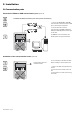
2. Installation 2.4 Communication ports Connection of RS232 or USB communication port (optional) The RS232 and USB communication ports cannot operate simultaneously. 1 - Connect the RS232 (33) or USB (34) communication cable to the serial or USB port on the computer equipment. 34 2 - Connect the other end of the communication cable (33) or (34) to the USB (1) or RS232 (2) communication port on the UPS. 33 The UPS can now communicate with EATON power management software.
2. Installation 2.5 Connections with a FlexPDU (Power Distribution Unit) module (optional) 1 - Connect the UPS socket (10) to the ACpower source using the cable (31) supplied. 8 2 - Connect the input socket on the FlexPDU module (48) to the UPS outlet (7) using the cable (41) supplied. The cable and the connectors are marked in red. 7 9 10 31 41 3 - Connect the equipment to the outlets (45), (46) and (47) on the FlexPDU module. These outlets differ, depending on the version of the FlexPDU module.
2. Installation 51 The HotSwap MBP module has a rotary switch (53) with two positions: Normal - the load is supplied by the UPS, Bypass - the load is supplied directly by the AC-power source. BY PASS SWITCH Normal UPS ON OK to switch By-pass HotSwap MBP-module operation 52 53 UPS start-up with the HotSwap MBP module 1 - Check that the UPS is correctly connected to the HotSwap MBP module. 2 - Set switch (53) to the Normal position.
3. Operation 3.1 Start-up and normal operation For the initial start, AC input power must be present to detect any wiring errors. Subsequently, the UPS can start even if AC input power is not present. 20 21 22 Press button (27) for approximately 1 second. ◗ The buzzer beeps once and all the LEDs go ON simultaneously. ◗ The buzzer then beeps twice during the self-test, then button (27) remains ON, indicating that the load outputs are supplied. The connected devices are protected by the UPS. LED (20) is ON.
3. Operation End of battery backup time ◗ ◗ All the LEDs go OFF. The audio alarms stops. The UPS is completely shut down. 3.3 Return of AC input power Following an outage, the UPS restarts automatically when AC input power returns (unless the restart function was disabled via UPS personalisation) and the load is again supplied. 3.4 UPS shutdown 20 21 22 Press button (27) for approximately 2 seconds. The devices connected to the UPS are no longer supplied. ESC 27 3.
3. Operation 5 ROO Contact open: shut down of UPS Contact closed: start-up of UPS (UPS connected to the network and network energized) Note: local On/Off control via button (27) has priority over the remote control order. 5 RPO Contact open: shut down of UPS To return to normal operation, deactivate the external remote shut down contact and restart the UPS using button (27). 4 - Plug connector (5) into the back of the UPS.
4. Access to measurements and personalisation data 4.1 Display menus arrangement Status and Alarms Status and Alarms Measurements UPS input measurements UPS output measurements Battery measurements Personalisation Local personalisation Output personalisation ON/OFF personalisation Battery personnalisation 4.2 Access to measurements Press the scroll button (25) to access any status conditions and alarms, then the measurements for voltage, current, frequency, power output and battery backup time. 4.
4. Access to measurements and personalisation data Output personalisation Function Factory setting Output voltage (1) Other available settings Comments 230 Volts AC 200/208/220/240 Volts AC Disabled Enabled The connected devices are never transferred to the bypass. Output frequency (1) Automatic selection 50 or 60 Hz User selectable only if the frequency-converter function is enabled.
5. Maintenance 5.1 Troubleshooting If LED (21) or (22) is ON, a fault or an alarm has occurred. Use the escape button (24) to stop the audio alarm. Indication 34007776EN/AD - Page 18 Diagnostic Correction 1 The UPS does not start, the alphanumeric display indicates: COLD START NOK CHECK AC WIRING The AC input power is not connected or is connected to the UPS output. Check the UPS is correctly connected to the AC input power. 2 LED (22) is ON, the SWF LED (11) at the rear of the UPS is ON.
5. Maintenance Troubleshooting a UPS equipped with the HotSwap MBP module Indication Diagnostic Correction 12 The load is no longer supplied when ◗ The protected devices are Check the wiring between the UPS the rotary switch (49) on the and the HotSwap MBP module connected to the UPS output HotSwap MBP module is set to the (see section 2.6). instead of to the HotSwap MBP Bypass position. module. ◗ The AC-power cord is connected to the UPS input instead of to the HotSwap MBP module.
5. Maintenance D - Remove the metal protection cover in front of the battery (two screws). D E - Pull the plastic tab to remove the battery block and replace it. E Mounting the new battery module Carry out the above instructions in reverse order. ◗ ◗ To ensure safety and high performance, use only batteries supplied by EATON. Take care to firmly press together the two parts of the connector during remounting. 5.
5. Maintenance 5.4 Training centre To fully master operation of your EATON product and carry out level 1 servicing, see our complete range of technical training courses, available in both French and English. For further information, please visit our website: www.eaton.
6. Appendices 6.1 Technical specifications Output power EX 2200 EX 3000 EX 3000 XL 2200 VA (1) / 1980 W 3000 VA (2) / 2700 W (3) 3000 VA (2) / 2700 W (3) Electrical supply network Rated input voltage ◗ Input voltage range ◗ Frequency ◗ Power factor ◗ Leakage current Single phase 230 V 110 / 140 / 200 V to 284 V (4) 50/60 Hz (autoselection) > 0.
6. Appendices 6.2 Glossary Bypass AC input Bypass line from the AC-power source, controlled by the UPS, used to directly supply the load if an overload or a malfunction occurs on the UPS. Backup time Time during which the load can be supplied by the UPS operating on battery power. Battery test Internal UPS test to check battery status. Cold start The devices connected to the UPS can be started even if AC input power is not available. The UPS operates on battery power alone.
www.eaton.