
User`s guide


V3-T9-256 Volume 3—Power Distribution and Control Assemblies CA08100004E—November 2013 www.eaton.com
9
9
9
9
9
9
9
9
9
9
9
9
9
9
9
9
9
9
9
9
9
9
9
9
9
9
9
9
9
9
9.4
Metering Devices, Protective Relays, Software and Connectivity
Protective Relays
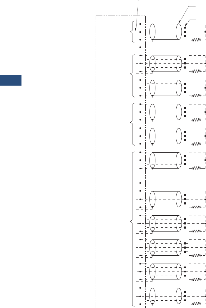
Wiring Diagram
RTD Wiring (Three-Lead Type)
Note
Showing a typical three-lead type RTD wiring connection.
Universal
RTD Module
Do not connect cable’s shield and drain wire
at this end. Use tape to insulate.
Connect cable’s shield
and drain wire here.
Note: Wiring between motor RTDs
and RTD Module must be
three-wire shielded cable.
Unused channels should
be shorted.
1. Each shielded cable’s conductors must be connected on Universal RTD Module as shown.
2. Use of three-lead RTDs is recommended.
3. RTDs must not be grounded at the motor, and no common connections between RTDs should be made at the
Universal RTD Module or the motor.
4.
Terminal 16 or 32 should be connected to a suitable earth ground.
Motor
Bearings
Motor
Windings
Auxiliary
Load
Bearings
Motor terminals
35
27
29
28
31
30
34
33
32
22
17
19
18
21
20
34
23
26
25
8
9
11
10
12
14
13
15
16
1
2
3
5
4
6
7