
User`s guide


Volume 3—Power Distribution and Control Assemblies CA08100004E—November 2013 www.eaton.com V3-T9-219
9
9
9
9
9
9
9
9
9
9
9
9
9
9
9
9
9
9
9
9
9
9
9
9
9
9
9
9
9
9
9.4
Metering Devices, Protective Relays, Software and Connectivity
Protective Relays
Wiring Diagrams
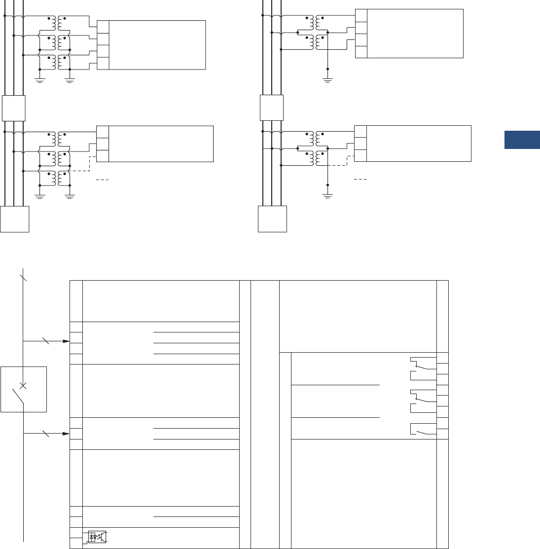
Three-Line Wye Three-Line Delta
VR-300
A
VT
BC
L1
L2
L3
N
1
Measuring
Voltage
234
52
VT
L1
L2
L3
707172
a) Not Measured
a)
Load
Synchronizing
Voltage
Not Required
A
VT
BC
L1
L2
L3
N
1
Measuring
Voltage
234
52
VT
L1
L2
L3
707172
a)
Load
Synchronizing
Voltage
a) Not Measured
Not Required
The synchronizing voltage must be connected
3-phase if the measuring voltage is connected
3-phase (N not connected). If the measuring
voltage is connected 4-phase (L1, L2, L3, N),
the synchronizing voltage may be connected
2-phase (L1-L2). L3 is connected only for
compensation and is not measured.
0 Vdc
Blocking of protective functions
or remote acknowledgement.
Relay 1
(Ready for Operation)
Relay 2
Subject to Technical Modications.
2/3
Synchronizing System (Fixed)
CB
5678
VR-300 (Multi-Function Voltage Relay)
90 to 250 Vac/dc
Synchronizing Voltage L1
Synchronizing Voltage L2
Synchronizing Voltage L3
70 71 72
Measuring Voltage L1
Measuring Voltage L2
Measuring Voltage L3
(Measuring Voltage N)
1234
910111213141516
Relay 3
(Fixed to synch-check
zero voltage congurable)
Measuring Voltage
3-Wire or
4-Wire System
Supervised System
(Variable) 3/4
3/4
Measuring Voltage: 100 Vac
The socket for the PC parameterization
is situated on the side of the unit. This is
where the DPC must be plugged in.
Not Measured.