
Installation Guide

First Location Second Location
3 traveler wires are required
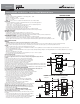
DIAGRAM 2A: SWITCH IN LOCATION WITH HOT WIRE
3-Way Switch
OS306U or VS306U Sensor
Hot
Black
Hot
Black
Black
3-Way
Blue
NeutralNeutral
Neutral
White
White
Light Fixture
Black Traveler
Red Traveler
White Traveler
Red
Output
Ground
Bare
Green
Ground
Bare
Green
Catalog # OS306U Auto On Sensor Catalog # VS306U Manual On Sensor
SPECIFICATIONS
• 120V/AC, 60 Hz
• Incandescent/Tungsten/Halogen/LED/Electronic Low Voltage (ELV) — 600W
• Magnetic Low Voltage — 600VA
• Fluorescent, Compact Fluorescent — 5.0A/600W
• Motor Load — 1/6 HP
• NOTE - A Ground connection is required in the wallbox where the sensor will be installed
DESCRIPTION
• This Sensor Wall Switch can replace a standard wall switch in any of the following applications:
• Single location – one Single Pole switch.
• Two location – one location is the sensor and the other location is a standard 3-way switch
• Two location – replace both 3-Way switches with sensors.
• The OS306U turns on automatically when a person enters the room.
• The VS306U requires manual activation to turn on the lights.
• Both OS306U and VS306U will automatically turn off lights after a selectable time delay.
• OS306U includes a light level adjustment for daylight to prevent motion from turning on the lights.
OPERATION INSTRUCTIONS
Auto ON Sensor – OS306U:
• OS306U will turn on lights automatically when a person enters the room.
• Lights will turn off automatically when no motion is detected after a selectable time delay.
• The selectable time delays are 5 seconds (Test Mode), 5 minutes (factory default), 10 minutes, 20 minutes and 30 minutes.
Manual ON Sensor – VS306U:
• The VS306U must be turned on manually with the ON/OFF button.
• Lights will turn off automatically when no motion is detected after a selectable time delay.
• The selectable time delays are 5 seconds (Test Mode), 5 minutes, 10 minutes, 20 minutes and 30 minutes (factory default).
• When the lights have turned off due to a lack of motion, the lights will turn ON automatically if motion is detected within 30 seconds.
INSTALLATION INSTRUCTIONS
WARNING:
• Turn OFF circuit breaker or remove fuse(s) and verify that power is off before wiring.
• Never wire any electrical device with power turned on. Wiring the device with the power on may cause permanent damage to the device and void the warranty.
• If you are unsure about any part of these instructions, or if the wiring does not match the descriptions given, you should call a qualified electrician.
CAUTION:
• Must be installed and used in accordance with all applicable electrical codes.
• If a bare copper or green ground connection is not available in the wallbox, contact a qualified electrician for installation. Do not install without proper ground connections.
• Do not exceed maximum device ratings.
• For use ONLY with permanently installed fixtures of these types: Incandescent/Tungsten/Halogen, Magnetic Low Voltage (MLV), Electronic Low Voltage (ELV), Fluorescent, Compact
Fluorescent, LED.
• May also be used with motors up to 1/6 HP.
• To avoid overheating and possible damage to other equipment, do not use to control receptacles.
• Use only #14 or #12 copper wire with these devices.
Installing OS306U & VS306U
Refer to the wiring diagrams and install the sensor according to these directions.
For sing
le pole applications, wire the sensor switch according to wiring diagram #1 using the wire nuts
provided.
1. The sensor black wire will connect to the hot wire (black) in the wallbox.
2. The sensor red wire will connect to the wire which goes to the light fixture.
3. The sensor blue wire is not used and should be capped off with a wire nut.
4. The sensor green wire will connect to the ground wire in the wallbox.
5. Install the sensor loosely using the mounting screws provided.
6. Apply power and wait one minute. Verify that the sensor works by pushing the ON/OFF button to verify the lights
turn on and off. You must wait 2 seconds between button presses. If the lights do not work, then turn off the power
and swap the connections on the sensor black and red wires.
7. Apply power again and verify that the sensor works by pushing the ON/OFF button to verify the lights turn on and off.
8. Turn power OFF and go to COMPLETING THE INSTALLATION.
For 3-way applications, wire the sensor switch according to wiring diagram #2A or 2B using the wire
nuts
provided. The sensor may be placed at either end of the 3-way circuit.
1. Remove the existing switch in the location where the sensor will be installed.
a. The sensor black wire will connect to either one of the black wires in the wallbox.
b. The sensor red wire will connect to the other black wire in the wall box.
c. The sensor blue wire will connect to the red traveler wire in the wallbox
d. The sensor green wire will connect to the ground wire in the wallbox.
e. Install the sensor loosely using the mounting screws provided.
2. Remove the existing switch in the other 3-way location.
a. Connect the two black wires together.
b. Connect the bare ground wire in the wallbox to the common terminal
(usually a black screw or a marking such as COM or COMMON near the
terminal) on the 3-way switch.
c. Connect the red wire to either of the other switch terminals.
d. Re-install the 3-way switch and tighten securely.
3. Apply power and wait one minute. Verify that the sensor works by pushing the
ON/OFF button. You must wait 2 seconds between button presses. The lights
should turn ON and OFF. If the lights do not work, then turn the power off and
swap the connections to the sensor black and red wires.
4. Apply power again and verify the sensor works by pushing the ON/OFF button
to verify the lights turn ON and OFF.
5. Turn power OFF and go to COMPLETING THE INSTALLATION.
For 2 sensor applications, wire the sensor switches according to w
iring
diagram #3 using the wire nuts provided.
1. Remove the existing switch in the 3-way location where the first sensor will
be installed.
a. The sensor black wire will connect to the two black wires in the wallbox.
b. The sensor red wire will connect to the red wire in the wallbox.
c. The sensor blue wire is not used and should be capped off with a wire nut.
d. The sensor green wire will connect to the ground wire in the wallbox.
e. Install the sensor loosely using the mounting screws provided.
ENGLISH IN U.S.A.:Cooper Wiring Devices, 203 Cooper Circle, Peachtree City, GA 30269 • 866-853-4293
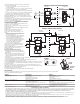
DIAGRAM 1: SENSOR IN ONE LOCATION
OS306U or VS306U Sensor
Light Fixture
White
Neutral
White
Neutral
Ground
Bare Green
3-Way
Blue
Black
Hot
Black
Hot
Black
Output
Red
0
15’
MAJOR MOTION
450 SQ. FT.
25’
0
COVERAGE PATTERN
8’
12’
8’
12’
LOWCOST-PTA (REV. B)