
User manual

LCX9000 Liquid-Cooled Drives User Manual
3-12 For more information visit: www.eaton.com
MN04005001E
September 2007
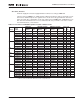
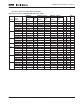
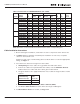
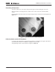
Figure 3-1: Maximum Terminal Stresses
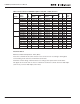
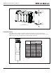
Installation Space
Enough free space must be left above and below the drive to ensure practical and
appropriate electrical and cooling connections. The minimum dimensions are given in the
table below. No space is required to the left and right of the drive.
Figure 3-2: Installation Space
2,3 kN
2,3 kN
2,3 kN
2,3 kN
2,3 kN
2,3 kN
2,3 kN
2,3 kN
AC Drives
Maximum Terminal Stress
1 kN
1 kN
A
B
Distance to the cable connection block. Additional
space must be reserved for ferrite rings, if used.
See Page 3-1.
Chassis
Approximate Dimensions
in Inches (mm)
AB
CH3 3.94 (100) 5.91 (150)
CH4 3.94 (100) 7.87 (200)
CH5 3.94 (100) 7.87 (200)
CH61 3.94 (100) 11.81 (300)
CH62 3.94 (100) 15.75 (400)
CH63 7.87 (200) 15.75 (400)
CH64 7.87 (200) 19.69 (500)
CH72 7.87 (200) 15.75 (400)
CH74 7.87 (200) 19.69 (500)