
User manual

LCX9000 Liquid-Cooled Drives User Manual
2-28 For more information visit: www.eaton.com
MN04005001E
September 2007
2. Connection of cables:
Types CHK0023N6A0, CHK0038N6A0, CHK0062N6A0 (chokes with terminal blocks)
The terminals are marked with letters U, V, W and X, Y and Z such that terminals U and
X, V and Y as well as W and Z form pairs of which one is an input and the other an
output. Furthermore, terminals U, V and W must all be used as either input or output.
The same applies to terminals X, Y and Z. See Figure 2-24.
Example: If you connect the mains cable of one phase to terminal X, the other two
phases must be connected to Y and Z. Accordingly, the choke output cables are
connected to their corresponding input pairs: phase 1 ➔ U, phase 2 ➔ V and
phase 3 ➔ W.
Other types (chokes with busbar connection)
Connect the mains cables to the upper busbar connectors (see Figures 2-25 and 2-26)
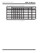
with bolts. The cables to the drive are bolted to the lower connectors. See Table 2-18 for
bolt sizes.
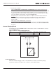
Inverter Charging Circuit
The charging circuit of LCX9000 Liquid-Cooled inverters can be controlled with a contactor
and a charging resistor.
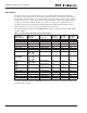
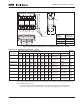
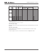
Table 2-19: Resistor Used for Charging Circuits
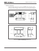
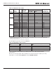
Figure 2-27: Charging Circuit
Control with Contactor
When the inverter charging circuit is controlled with a contactor, an auxiliary voltage
transformer must be used. Note local conditions of the supply voltage.
Type Nominal Rating T=350°; @25°C Max Voltage Resistance, ±10%
Danothrm ZRF 30/165 165W 1200V 33Ω
DC
+
DC
-
U
V
W
DC
+
DC
-
C
C1