
User manual

LCX9000 Liquid-Cooled Drives User Manual
MN04005001E
For more information visit: www.eaton.com
1-11
September 2007
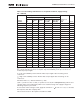
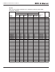
I
th
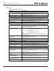
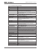
= Thermal maximum continuous RMS current. Dimensioning can be done according to
this current if the process does not require any overloadability or the process does not
include any torque ripple.
I
L
= Low overloadability current. Allows +10% torque ripple. 10% exceeding can be
continuous.
I
H
= High overloadability current. Allows +50% torque ripple. 50% exceeding can be
continuous.
All values with cosϕ = 0.83 and efficiency = 97%
c/a/T: c = power loss into coolant; a = power loss into air; T = total power loss
All power losses obtained using max. supply voltage I
th
and switching frequency of 3.6 kHz
and Closed Loop control mode. All power losses are worse case losses.
If some other mains voltage is used, apply the formula
to calculate the Liquid-Cooled drive electrical output power.
If the motor is continuously run (besides start and stop ramps) at frequencies below 5 Hz, pay
attention to the drive dimensioning for low frequencies, i.e. maximum I
H
= 0.66* I
th
or choose
drive according to I
H
. Check the rating with your Eaton distributor.
Drive overrating may also be necessary if the process requires high starting torque.
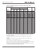
The voltage classes for the inverter units used in the tables above have been defined as
follows:
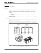
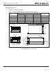
The enclosure class of all inverter units is IP00.
Input 540V DC = Rectified 400V AC supply
Input 675V DC = Rectified 500V AC supply
DC P = (Un/1.35) *
3
*In*cos
ϕ
*eff%