
User manual

LCX9000 Liquid-Cooled Drives User Manual
1-6 For more information visit: www.eaton.com
MN04005001E
September 2007
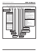
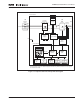
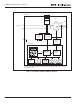
Figure 1-2: Liquid-Cooled Drive DC Block Diagram
Control
I/O
Motor and
Application
Control
Control Keypad
Control Module
PE
Power Module
RS-232
Control
I/O
Measurements
Motor
Control
ASIC
Gate
Drivers
Power
Supply
Control
I/O
Control
I/O
Control
I/O
Brake *
Chopper
Brake Resistor *
3~
U/T1
V/T2
W/T3
=
Motor
IGBT
Inverter
Current
Sensors
* Brake resistor is available as optional equipment for all sizes (CH3 to CH7).
An internal brake chopper is standard equipment in CH3 only, while in all other sizes it is optional
and installed externally.
+
-
DC Supply
(2)
(3)