
Technical data


June 2008
CA08102001E For more information visit: www.eaton.com
40-9
Adjustable Frequency Drives
40
MVX9000
Open Drives
Technical Data and
Specifications
Output Ratings
■ Horsepower;
❑ 90 – 132V, 1/4 – 1 hp
❑ 200 – 240V: 1/2 – 7-1/2 hp
❑ 380 – 480V: 1 – 10 hp
❑ 425 – 660V: 1 – 10 hp
■ Frequency Range: 0.1 – 400 Hz
■ Overload Rating: 150% for 60 seconds
■ Frequency Resolution:
❑ Digital: 0.1 Hz
❑ Analog: Max. (Set Frequency/1000) Hz
■ Frequency Accuracy
❑ Digital: ± 0.01% of max. frequency
❑ Analog: ± 0.2% of max. frequency
■ Undervoltage Carryover Limit:
0.3 to 25 seconds
Motor Performance
■ Motor Control: Sensorless Vector
■ Constant and Variable Torque:
Standard
■ Speed Regulation: 0.5% of base speed
Input Power
■ Voltage at 50/60 Hz ± 3 Hz
❑ 100V – 120V, -10% +10% / 1-phase
❑ 200V – 240V, -10% +5% / 1-phase
❑ 200V – 240V, -10% +5% / 3-phase
❑ 380V – 480V, -10% +10% / 3-phase
❑ 500V – 600V, -15% +10% / 3-phase
■ Displacement Power Factor:
Better than 0.95
■ Efficiency: Typically greater than 95%
Design Type
■ Microprocessor: 32-Bit
■ Converter Type: Diode
■ Inverter Type: Insulated Gate Bipolar
Transistor
■ Waveform: Sensorless Vector
Environment
■ Operating Temperature:
❑ -10°C to +50°C
❑ -10°C to +40°C (above 7-1/2 hp)
■ Humidity: 20 to 90% non-condensing
■ Maximum Elevation: 1000 meters
(3300 ft.)
Codes and Standards
■ NEMA, IEEE, NEC: Design Standards
■ UL Listed
■ cUL Listed
■ CE Marked (Requires EMI filter)
Enclosure
■ Standard: Protected Chassis (IP20)
Protective Features
■ Ground Fault: Standard
■ Overload Protection: Standard
■ Overcurrent: Standard
■ Overvoltage: Standard
■ Undervoltage: Standard
■ Overtemperature: Standard
■ Overload Limit: Standard
Set Up Adjustments, Performance
Features, Operator Control and
External Interface
Keypad
■ Alphanumeric Display:
Standard, 1 x 4 character
■ Digital Indications:
Frequency (Hz), Motor Current
(amps), User-Defined RUN/STOP,
FORWARD/REVERSE and Parameters
■ Diagnostics: Last 3 trips with cause
■ LED Status Indicators: 8
(RUN/STOP, FORWARD/REVERSE,
Hz, Amps, User Defined, and Input
Speed)
■ Operator Functions:
START/STOP, Speed control (digital
or potentiometer), RESET, SETUP
Keys and ENTER.
I/O Terminal Block
■ Analog Inputs:
❑ 2 Inputs: 0 – 10V DC, 4 – 20 mA
❑ Potentiometer: 1K ohm to 2K ohm
❑ Analog Voltage: Nominal 10V DC
(10K ohm input impedance)
❑ Analog Current: Nominal 4 – 20
mA (250 ohm)
■ Digital Inputs: 6 Programmable
Inputs
■ Digital Outputs: 1 Programmable
Open collector and 1 Form C Relay
contact
■ Analog Monitor Output:
❑ Analog meter – frequency or
output current
■ Dynamic Brake Chopper
Programmable Parameters
■ Out of the Box: Factory settings
loaded for quick start-up.
■ Accel. and Decel.: 2 separately
adjustable Linear or S Curve times:
0.1 – 3000 seconds
■ Auto Restart:
Overcurrent, overvoltage and
undervoltage with 4 selectable retry
restart modes
■ DC Injection Braking
■ External Fault: Terminal input
■ Jog: Terminal input
■ Fault Reset: STOP/RESET or terminal
input
■ I/O: NO/NC Selectable
■ Jump Frequencies: 3 (with adjustable
width)
■ Parameter Security: Programmable
software lock
■ Preset Speeds: 7 preset speeds
■ PID Controller: PID process control
■ Reversing: Keypad or terminal
■ Speed Setting: Keypad, terminal
or pot
■ START/STOP Control: Keypad or
terminal
■ Stop Modes: Decel, coast or DC
injection
Reliability
■ Pretested Components: Standard
■ Surface Mount Technology:
Standard (PCBs)
■ Computerized Testing: Standard
■ Final Test with Full Load: Standard
■ Eaton’s Cutler-Hammer Engineering
Systems and Service: National net-
work of AF drive specialists
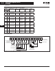
Table 40-6. Heat Loss Data
Model Watts Lost
at 9 kHz
Model Watts Lost
at 9 kHz
Watts Lost
at 6 kHz
MVXF25A0-1 (1-phase)
MVXF50A0-1 (1-phase)
MVX001A0-1 (1-phase)
20
20
38
MVX001A0-4
MVX002A0-4
MVX003A0-4
38
75
110
—
—
—
MVXF50A0-2 (1-phase)
MVXF50A0-2 (3-phase)
MVX001A0-2 (1-phase)
20
20
38
MVX005A0-4
MVX007A0-4
MVX010A0-4
185
275
375
—
—
—
MVX001A0-2 (3-phase)
MVX002A0-2 (1-phase)
MVX002A0-2 (3-phase)
38
75
75
MVX001A0-5
MVX002A0-5
MVX003A0-5
—
—
—
30
58
83
MVX003A0-2 (1-phase)
MVX003A0-2 (3-phase)
MVX005A0-2
MVX007A0-2
110
110
185
275
MVX005A0-5
MVX007A0-5
MVX010A0-5
—
—
—
—
—
132
191
211
—