
Technical data


June 2008
CA08102001E For more information visit: www.eaton.com
40-5
Adjustable Frequency Drives
40
NFX9000
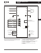
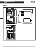
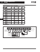
Figure 40-2. Basic Wiring Diagram
Note: Do not plug a modem or telephone line to the RS-485 commu-
nication port, permanent damage may result. Terminals 1 and 2 are
the power sources for the optional copy keypad and should not be
used while using RS-485 communication.
■ Use power terminals R/L1 and S/L2 for single-phase
connection to models: NFXF25A0-1, NFXF50A0-1,
NFXF25A0-2, NFXF50A0-2 or NFX001A0-2.
■ Use power terminals R/L1, S/L2 and T/L3 for three-phase
connection to models: NFXF25A0-2, NFXF50A0-2,
NFX001A0-2 or NFX002A0-2.
■ Single-phase power must not be used for model
NFX002A0-2.
U/T1
6
←
1
RS-485
Communication
Port
RA
RC
Relay Output Contacts
120V AC/28V DC 3A
Factory Default: Fault Indication
Main Circuit
(Power) Terminals
1 :
+
EV
2 : GND
3 : SG
-
4 : SG
+
+
18V
Factory Default Settings
DI1
4.7 KΩ
Forward/Stop
RJ-11
V/T2
Motor
W/T3
R/L1
S/L2
T/L3
R/L1
S/L2
T/L3
IM
3-Phase
Control Circuit
Terminals
Shielded Leads
+
18V
DI2
4.7 KΩ
Reverse/Stop
+
18V
DI3
4.7 KΩ
Reset
+
18V
DI4
GND
4.7 KΩ
Multi-Step 1
Common Signal
Power Supply for Potentiometer
+
10V 10 mA (Max.)
+
10V
Master Freq. Setting
3
2
Analog Voltage
0 ~ 10V DC
Analog Current
4 ~ 20 mA
AVI
GND
1
VR