
Technical data


June 2008
CA08102001E For more information visit: www.eaton.com
40-213
Adjustable Frequency Drives
40
CFX9000
Enclosed Drives
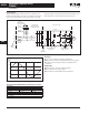
Figure 40-117. Oneline Diagram for Harmonic Analysis
The best way to estimate AFD harmonic contribution to an electrical system is to perform a harmonic analysis based on known system
characteristics. The oneline in this Figure would provide the data to complete the calculations.
Terms
■ PCC (Point of Common Coupling) is defined as the electri-
cal connecting point between the utility and multiple cus-
tomers per the specifications in IEEE 519.
■ POA (Point of Analysis) is defined as where the harmonic
calculations are taken.
An oscilloscope can make all measurements at the PCC or
POA to do an on-site harmonic evaluation.
Harmonic Reduction Methods to Meet IEEE 519
1. Line Reactor
A line reactor is a 3-phase series inductance on the line side
of an AFD. If a line reactor is applied on all AFDs, it is possi-
ble to meet IEEE guidelines where 10 – 25% of system loads
are AFDs, depending on the stiffness of the line and the
value of line reactance. Line reactors are available in various
values of percent impedance, most typically 1 – 1.5%,
3% and 5%. (Note: the 9000X drives come standard with a
nominal 3% input impedance.)
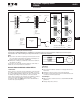
Figure 40-118. Line Reactor
Advantages
■ Low cost
■ Can provide moderate reduction in voltage and current
harmonics
■ Available in various values of percent impedance
■ Provides increased input protection for AFD and its semi-
conductors from line transients
Disadvantages
■ May not reduce harmonic levels to below IEEE 519-1992
guidelines
■ Voltage drop due to IR loss
____Volts ____Volts
____Volts
____KVA
____Isc
____Impedance
PCC
Utility Side
Utility Side
Transformer
____Volts ____Volts
____Volts
____KVA
____Isc
____Impedance
Customer
Transformer
Customer
Generator
____Volts
____KVA
____Isc
____Impedance
Source A
Source B
Generator
Set
AC
Motor
AC
Motor
AC
Motor
Total Linear Motor Loads
Total Nonlinear Drive Loads
____AMPS
____AMPS
AC
Motor
AC
Motor
AC
Motor
AFD Motor