
Technical data


June 2008
CA08102001E For more information visit: www.eaton.com
40-211
Adjustable Frequency Drives
40
CFX9000
Enclosed Drives
Application Description
Designed to meet the IEEE 519-1992 requirements for
ha
rm
onic distortion, the CFX9000 is an excellent choice for
small and midsize drives applications where harmonics are
a concern.
What Are Harmonics?
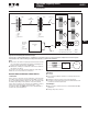
Take a perfect wave with a fundamental frequency of 60 Hz, which
is close to what is supplied by the power company.
Figure 40-112. Perfect Wave
Add a second wave that is five times the fundamental
frequency — 300 Hz (Typical of frequency added to the
line by a fluorescent light).
Figure 40-113. Second Wave
Combine the two waves. The result is a 60 Hz supply rich in fifth
harmonics.
Figure 40-114. Resulting Supply
What Causes Harmonics?
Harmonics are the result of nonlinear loads that convert
AC line voltage to DC. Examples of equipment that are
non-linear loads are listed below:
■ AC variable frequency drives
■ DC drives
■ Fluorescence lighting, computers, UPS systems
■ Industrial washing machines, punch presses, welders, etc.
How Can Harmonics Due to VFDs Be Diminished?
By applying drives from the Eaton Clean Power Drives
Fa
mi
ly; The HCX9000, CFX9000 and CPX9000.
What Are Linear Loads?
Linear loads are primarily devices that run across the line and
do not add harmonics. Motors are prime examples. The
downside to having large motor linear loads is that they draw
more energy than a VFD, because of their inability to control
motor speed. In most applications there is a turn down valve
used with the motor which will reduce the flow of the mate-
rial, without significantly reducing the load to the motor.
While this provides some measure of speed control, it is
extremely inefficient.
Why Be Concerned About Harmonics?
1. Installation and utility costs increase. Harmonics cause
damage to transformers and lower efficiencies due to
the IR loss. These losses can become significant (from
16.6 – 21.6%) which can have a dramatic effect on the
HVAC systems that are controlling the temperatures of
the building where the transformer and drive equipment
reside.
2. Downtime and loss of productivity. Telephones and
data transmissions links may not be guaranteed to work
on the same power grids polluted with harmonics.
3. Downtime and nuisance trips of drives and other equip-
ment. Emergency generators have up to (3) three times
the impedance that is found in a conventional utility
source. Thus the harmonic voltage can be up to three
times as large, causing risk of operation problems.
4. Larger motors must be used. Motors running across the
line that are connected on polluted power distribution
grids can overheat or operate at lower efficiency due to
harmonics.
5. Higher installation costs. Transformers and power
equipment must be oversized to accommodate the loss
of efficiencies. This is due to the harmonic currents cir-
culating through the distribution without performing
useful work.
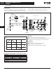
How Does a VFD Convert 3-Phase AC to a Variable
Output Voltage and Frequency?
The 6-pulse VFD: The majority of all conventional drives that
are built consist of a 6-pulse configuration. Figure 40-115
represents a 6-diode rectifier design that converts three-phase
utility power to DC. The inverter section uses IGBTs to convert
DC power to a simulated AC sine wave that can vary in
frequency from 0 – 400 Hz.
f(x) = sin(x)
Volts
(v)
Time
(t)
f(x) =
sin(5x)
5
Volts
(v)
Time
(t)
f(x) = sin(x) +
Volts
(v)
Time
(t)
sin(5x)
5