
Technical data


June 2008
CA08102001E For more information visit: www.eaton.com
40-115
Adjustable Frequency Drives
40
SVX9000
VFD Pump Panels
Control/Communication Option Descriptions
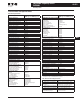
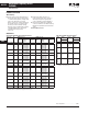
Table 40-167. Available Control/Communications Options
Note: For availability, see Product Selection for base drive voltage required.
Option Description Option
Type
K1 Door-Mounted Speed Potentiometer — Provides the SVX9000 with the ability to adjust the frequency reference using a door-
mounted potentiometer. This option uses the 10V DC reference to generate a 0 – 10V signal at the analog voltage input signal
terminal. When the HOA bypass option is added, the speed is controlled when the HOA switch is in the hand position. Without
the HOA bypass option, a 2-position switch (labeled local/remote) is provided on the keypad to select speed reference from the Speed
Potentiometer or a remote speed signal.
Control
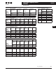
K2 Door-Mounted Speed Potentiometer with HOA Selector Switch — Provides the SVX9000 with the ability to start/stop and adjust
the speed reference from door-mounted control devices or remotely from customer supplied inputs. In HAND position, the drive
will start and the speed is controlled by the door-mounted speed potentiometer. The drive will be disabled in the OFF position.
When AUTO is selected, the drive run and speed control commands are via user-supplied dry contact and 4 – 20 mA signal.
Control
K5 Manual/Auto Speed Reference Switch — Provides a door-mounted selector switch for Manual/Auto speed reference. Control
K6 Start & Stop Pushbuttons (22 mm) — Start (green) and Stop (red). Provides door-mounted Start and Stop pushbuttons for either
bypass or non-bypass configurations.
Control
K9 (2) Factory Installed Auxiliary Contacts — Provides two NO/NC auxiliary contacts. Power
L1 Power On and Fault Pilot Lights — Provides a white power on light that indicates power to the enclosed cabinet and a red fault
light indicates a drive fault has occurred.
Light
L2 Bypass Pilot Lights for RB, RA Bypass Options — A green light indicates when the motor is running in inverter mode and an
amber light indicates when the motor is running in bypass mode. The lights are mounted on the enclosure door, above the
switches.
Addl. Bypass
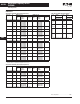
LD Green Stop Light (22 mm) — Provides a green light that indicates the drive is stopped. Light
LE Run Pilot Light (22 mm) — Provides a red run light that indicates the drive is running. Light
LU Misc. Light (22 mm) — Provides misc. “user defined” pilot light. User to define light function and color. Light
LW PTT (Push-To-Test) Light (22 mm) — Provides misc. “user defined” PTT pilot light. User to define light function and color. Light
LY Adder for LED Each — Changes light packages from standard incandescent bulb to LED style bulb. Light
P1 Input Disconnect Assembly Rated to 100 kAIC — High Interrupting Motor Circuit Protector (HMCP) that provides a means of
short circuit protection for the power cables between it and the SVX9000, and protection from high-level ground faults on the
power cable. Allows a convenient means of disconnecting the SVX9000 from the line and the operating mechanism can be padlocked
in the OFF position. This is factory mounted in the enclosure.
Input
P3 Input Line Fuses Rated to 200 kAIC — Provides high-level fault protection of the SVX9000 input power circuit from the load side
of the fuses to the input side of the power transistors. This option consists of three 200 kA fuses, which are factory mounted in
the enclosure.
Input
P7 MOV Surge Suppressor — Provides a Metal Oxide Varistor (MOV) connected to the line side terminals and is designed to clip
line side transients.
Input
P8 TVSS Transient Voltage Surge Suppressor — Provides transient voltage surge suppression of the unit. Consult factory for
ratings.
Input
PE Output Contactor — Provides a means for positive disconnection of the drive output from the motor terminals. The contactor
coil is controlled by the drive’s run or permissive logic. NC and NO auxiliary contacts rated at 10A, 600V AC are provided for
customer use. Bypass Option RA includes an Output Contactor as standard. This option includes a low VA 115V AC fused Control
Power Transformer and is factory mounted in the enclosure.
Output
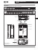
RA Manual HOA Bypass Controller — The Manual HAND/OFF/AUTO (HOA) — 3-contactor — bypass option provides a means of
bypassing the SVX9000, allowing the AC motor to be operated at full speed directly from the AC supply line. This option consists
of an input disconnect, a fused control power transformer, and a full voltage bypass starter with a door mounted HOA selector
switch and an INVERTER/BYPASS switch. The HOA switch provides the ability to start and stop the drive in the inverter mode.
For applications up to 100 hp, a Freedom Series IEC input contactor, a Freedom Series IEC output contactor, and a Freedom
Series IEC starter with a bimetallic overload relay is included. For applications above 100 hp, an Advantage input contactor, an
Advantage output contactor and an Advantage starter with electronic overload protection is included. The contactors are
mechanically and electrically interlocked (see power diagram on Page 40-112).
Bypass
S5 Floor Stand 22" — Converts a Size A or B, normally wall mounted enclosure to a floor standing enclosure with a height of
22" (558.8 mm).
Enclosure
S9 Space Heater without CPT — Prevents condensation from forming in the enclosure when the drive is inactive or in storage.
Includes a thermostat for variable temperature control. A 200W heater is installed in enclosures A and B, and 400W heater is
installed in enclosures C – D. Requires a customer supplied 115V remote supply source.
Enclosure
SA Space Heater with CPT— Prevents condensation from forming in the enclosure when the drive is inactive or in storage. Includes
a thermostat for variable temperature control. A 200W heater is installed in enclosures A and B, and 400W heater is installed in
enclosures C – D. Provided with CPT connected to load side of input disconnect.
Enclosure
SB Ice Cube Style Control Relay — Provides misc. “user defined” 4PDT control relay. Requires user to define functionality. Enclosure
SE On-Delay Timer (Delay on Make) — Provides misc. “user defined” time delay relay. Requires user to define functionality and
time setting requirement.
Enclosure
SF Off-Delay Timer (Delay on Break) — Provides misc. “user defined” time delay relay. Requires user to define functionality and
time setting requirement.
Enclosure