
Technical data


June 2008
CA08102001E For more information visit: www.eaton.com
40-11
Adjustable Frequency Drives
40
MVX9000
Open Drives
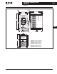
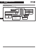
Figure 40-5. Basic Wiring Diagram
Note: Do not plug a modem or telephone line to the RS-485 commu-
nication port, permanent damage may result. Terminals 2 and 5 are
the power sources for the optional copy keypad and should not be
used while using RS-485 communication.
■ For single-phase application select correct model, and
select any of the two input terminals for main circuit
power.
Braking Resistor
(Optional)
L1
B1 B2
AC
Motor
Grounding Resistance
240V: Less Than 100Ω
480V: Less Than 10Ω
NO Relay Output
(120V AC/24V DC 5A)
NC Relay Output
(120V AC/24V DC 5A)
Factory Default: Inverter Fault
Digital Output (48V DC 50 mA)
Factory Default: Inverter Running
Factory Default:
Output Frequency
Analog Output
DC 0 to 10V
Main Circuit (Power) Terminals
Control Circuit Terminals
Shielded Leads
1,6: NC
2: GND
3: SG-
4: SG+
5: +EV
L2
L3
T1
T2
T3
RO3
DI1
DI2
DI3
DI4
DI5
DI6
COM
RO1
RO2
DOC
AO+
COM
COM
1
2
VR
3
AI2 (4 – 20 mA)
+10V 10 mA (Max)
Potentiometer
3K – 5KΩ
Reference Frequency Setting
Factory Default Is Potentiometer
Which Is on the Digital Keypad
Common
Reset
Preset Speed 3
Preset Speed 2
Preset Speed 1
Reverse/Forward
Start/Stop
Factory
Default
AI1 (0 – 10V DC)
RJ-11
RS-485
Series
Interface
6 to 1
DO1
L1
Main Circuit Power
L2
L3