
Technical data


June 2008
40-10
For more information visit: www.eaton.com CA08102001E
Adjustable Frequency Drives
40
MVX9000
Open Drives
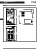
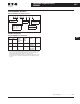
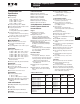
Table 40-7. All Braking Resistors & Braking Units Used in AC Drives
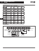
Wiring Diagrams
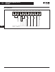
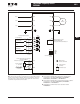
Figure 40-4. Control Terminal Wiring (Factory Settings)
Applicable
Motor
Braking Resistor
Kit P/N
Qty of
Resistors in
Kit & Wiring
Total Resistance
and Wattage
applied to MVX
Full Load
Torque (kgf-m)
of System
Braking
Torque @
10%ED
with Kit
hp kW
115V Series
1/4
1/2
1
.20
.37
.75
K13-000034-0821
K13-000034-0821
K13-000034-0821
1
1
1
80W 200Ω
80W 200Ω
80W 200Ω
.108
.216
.427
220%
220%
125%
230V Series
1/2
1
2
.37
.75
1.5
K13-000034-0821
K13-000034-0821
K13-000034-0824
1
1
1
80W 200Ω
80W 200Ω
300W 70Ω
.216
.427
.849
220%
125%
125%
3
5
7-1/2
2.2
3.7
5.5
K13-000034-0824
K13-000034-0825
K13-000034-0826
1
1
2 in Parallel
300W 70Ω
400W 40Ω
500W 30Ω
1.262
2.080
3.111
125%
125%
125%
480V Series
1
2
3
.75
1.5
2.2
K13-000034-0841
K13-000034-0843
K13-000034-0843
1
1
1
80W 750Ω
300W 250Ω
300W 250Ω
.427
.849
1.262
125%
125%
125%
5
7-1/2
10
3.7
5.5
7.5
K13-000034-0844
K13-000034-0845
K13-000034-0846
1
2 in Parallel
3 in Parallel
400W 150Ω
500W 100Ω
1000W 75Ω
2.080
3.111
4.148
125%
125%
125%
575V Series
1
2
3
.75
1.5
2.2
K13-000034-0851
K13-000034-0851
K13-000034-0852
1
1
—
300W 400Ω
300W 400Ω
600W 200Ω
.427
.849
1.262
125%
125%
125%
5
7-1/2
10
3.7
5.5
7.5
K13-000034-0852
K13-000034-0852
K13-000034-0853
—
—
—
600W 200Ω
600W 200Ω
2000W 100Ω
2.080
3.111
4.148
125%
125%
125%
RO3
NC Relay Output
4 – 20 mA
Factory Setting:
Inverter Fault
NO Relay Output
Forward/Stop
Reverse/Stop
Preset Speed 1
Preset Speed 2
Preset Speed 3
Reset
Factory Setting:
Inverter Running
Bias
Potentiometer
Digital Output
Full Scale Voltmeter:
0 to 10V DC
Factory Setting:
Output Frequency
RO2
RO1 DI1 DI2 DI3 DI4 DI5 DI6 COM AO+ AI1 +10V AI2 COM DO1 DOC