Adjustable Frequency Drives 40-1 Adjustable Frequency Drives June 2008 Contents Description Page NFX9000 Drives . . . . . . . . . . . . . . . . . . . . . . . . . . . . . . . . . . . . . . . . . . . . . . . MVX9000 Drives Open Drives . . . . . . . . . . . . . . . . . . . . . . . . . . . . . . . . . . . . . . . . . . . . . . . . Enclosed Drives . . . . . . . . . . . . . . . . . . . . . . . . . . . . . . . . . . . . . . . . . . . . . SLX9000 Drives Open Drives . . . . . . . . . . . . . . . . . . . . . .
40-2 Adjustable Frequency Drives NFX9000 June 2008 Product Description Contents Description NFX9000 Drives Product Description . . . . . . . Features and Benefits . . . . . Technical Data and Specifications . . . . . . . . . . Wiring Diagrams . . . . . . . . . Dimensions . . . . . . . . . . . . . Catalog Number Selection . . . . . . . . . . . . . . Product Selection . . . . . . . .
Adjustable Frequency Drives NFX9000 40-3 June 2008 Technical Data and Specifications Output Ratings ■ ■ ■ ■ ■ ■ Horsepower; ❑ 90V – 132V, 1/4 – 1/2 hp ❑ 200 – 240V: 1/2 – 2 hp Frequency Range: 0.1 – 400 Hz Overload Rating: 150% for 60 seconds Frequency Resolution: ❑ Digital: 0.1 Hz Frequency Accuracy ❑ Digital: ± 0.01% of max. frequency ❑ Analog: ± 0.2% of max. frequency Undervoltage Carryover Limit: 0.
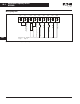
0-4 Adjustable Frequency Drives NFX9000 June 2008 Wiring Diagrams RA RC AVI DI1 DI2 DI3 DI4 GND Common Signal Digital Input Selection 3 Digital Input Selection 2 Multi-Function Input Selection 1 Multi-Function Assistant Terminal Analog Voltage, Current Frequency Command Power for Speed Setting 40 Relay Output Contact (120V AC/DC 28V 3A) Relay +10V Wire Gauge: 22 – 24 AWG Torque: 4 Kgf-cm Figure 40-1. Control Terminal Wiring (Factory Settings) For more information visit: www.eaton.
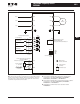
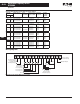
Adjustable Frequency Drives NFX9000 40-5 June 2008 R/L1 R/L1 U/T1 S/L2 S/L2 V/T2 IM 3-Phase T/L3 T/L3 W/T3 Motor +18V Factory Default Settings Forward/Stop DI1 Reverse/Stop DI2 Reset DI3 Multi-Step 1 DI4 40 4.7 KΩ 4.7 KΩ 4.7 KΩ 4.7 KΩ RA +18V Relay Output Contacts 120V AC/28V DC 3A Factory Default: Fault Indication +18V RC +18V RJ-11 Common Signal GND 6←1 RS-485 Communication Port Power Supply for Potentiometer +10V 10 mA (Max.) Master Freq.
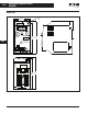
40-6 Adjustable Frequency Drives NFX9000 June 2008 Dimensions 0.20 (5.0) Dia. 2.68 (68.0) 2.20 (56.0) R/L1 S/L2 T/L3 STOP RUN FWD REV MODE RESET RUN STOP ENTER NFX9000 MIN. MAX. 0.5 HP 230V 40 ! 1 PHASE 4.72 5.20 (120.0) (132.0) WARNING RA RC +10V AVI D1 D2 D3 D4 GND RS-485 U/T1 V/T2W/T3 RS-485 5.04 4.86 (128.1) (123.4) Figure 40-3. 1/4 to 2 hp Drive Approximate Dimensions in Inches (mm) For more information visit: www.eaton.
Adjustable Frequency Drives NFX9000 40-7 June 2008 Catalog Number Selection Table 40-3. NFX9000 Catalog Numbering System N F X 0 0 1 A 0 - 2 Base Catalog Number Series A Voltage 1 = 115V AC 2 = 240V AC Horsepower F25 = F50 = 001 = 002 = 1/4 hp 1/2 hp 1 hp 2 hp Enclosure 0 = IP20 Product Selection Table 40-4. NFX9000 Basic Controller IP20 Description hp Volts Input Ampere Single-/ Three-Phase Rating Continuous Catalog Output Number Amp Rating 1/4 1/2 90 – 130 6.0/— 9.0/— 1.6 2.
40-8 Adjustable Frequency Drives MVX9000 June 2008 Open Drives Product Description Contents Description MVX9000 Open Drives Product Description . . . . . . . Features and Benefits . . . . . Technical Data and Specifications . . . . . . . . . . Wiring Diagrams . . . . . . . . . Dimensions . . . . . . . . . . . . . Catalog Number Selection . . . . . . . . . . . . . . Product Selection . . . . . . . . Options . . . . . . . . . . . . . . . . .
Adjustable Frequency Drives MVX9000 40-9 June 2008 Open Drives Technical Data and Specifications Output Ratings ■ ■ ■ ■ ■ ■ Horsepower; ❑ 90 – 132V, 1/4 – 1 hp ❑ 200 – 240V: 1/2 – 7-1/2 hp ❑ 380 – 480V: 1 – 10 hp ❑ 425 – 660V: 1 – 10 hp Frequency Range: 0.1 – 400 Hz Overload Rating: 150% for 60 seconds Frequency Resolution: ❑ Digital: 0.1 Hz ❑ Analog: Max. (Set Frequency/1000) Hz Frequency Accuracy ❑ Digital: ± 0.01% of max. frequency ❑ Analog: ± 0.2% of max.
Adjustable Frequency Drives MVX9000 40-10 June 2008 Open Drives Table 40-7. All Braking Resistors & Braking Units Used in AC Drives Applicable Motor hp Braking Resistor Kit P/N Qty of Total Resistance Resistors in and Wattage Kit & Wiring applied to MVX K13-000034-0821 K13-000034-0821 K13-000034-0821 1 1 1 80W 200Ω 80W 200Ω 80W 200Ω .108 .216 .427 220% 220% 125% kW Full Load Braking Torque (kgf-m) Torque @ of System 10%ED with Kit 115V Series 1/4 1/2 1 .20 .37 .75 230V Series 1/2 1 2 .37 .
Adjustable Frequency Drives MVX9000 40-11 June 2008 Open Drives Braking Resistor (Optional) Main Circuit Power L1 L2 L3 L1 L2 L3 B1 B2 T1 AC Motor T2 T3 Grounding Resistance 240V: Less Than 100Ω 480V: Less Than 10Ω RO3 Factory Default Start/Stop RO1 DI1 Reverse/Forward Preset Speed 1 Preset Speed 2 Preset Speed 3 Reset Factory Default: Inverter Fault NO Relay Output (120V AC/24V DC 5A) NC Relay Output (120V AC/24V DC 5A) RO2 DI2 DO1 DI3 Digital Output (48V DC 50 mA) DI4 DOC DI5 Factory
Adjustable Frequency Drives MVX9000 40-12 June 2008 Open Drives Dimensions Table 40-8. Approximate Dimensions and Shipping Weights for Basic Controller Description Horsepower 40 Dimensions in Inches (mm) Shipping Weight Lbs. (kg) Volts Width Height Depth 1/4 1/2 1 100 – 120 3.9 (100) 3.9 (100) 3.9 (100) 5.9 (151) 5.9 (151) 5.9 (151) 5.7 (145) 5.7 (145) 5.7 (145) 6.2 (2.8) 6.2 (2.8) 6.2 (2.8) 1/2 1 2 3 5 7-1/2 200 – 240 3.9 (100) 3.9 (100) 3.9 (100) 4.9 (100) 4.9 (125) 4.9 (125) 5.
Adjustable Frequency Drives MVX9000 40-13 June 2008 Open Drives .23 (5.8) Dia. Typ. 8.07 (205.0) 7.55 (191.7) 7.15 (181.5) .41 (10.5) 4.92 (125.0) 4.33 (110.0) 9.25 (235.0) 8.66 (220.0) 4.70 (119.5) 1.85 (46.9) .59 (15.0) MOTOR T1 T2 T3 .59 (15.0) 40 .10 (2.5) 3.48 (88.5) Braking B1 B2 7.15 (181.
40-14 Adjustable Frequency Drives MVX9000 June 2008 Open Drives 2.54 (64.6) 2.36 (60) 1.20 (30.5) .08 (2.0) .09 (2.3) Dia. x .19 (4.8) Deep Connection Hole for Extension Cable Screw (Typ. 2 Places) .92 (23.3) 3.46 (88) 1.63 (41.5) 2.22 (56.5) 1.81 (46) 1.48 (37.6) M4 P .03 (.7) x .19 (4.8) Deep for Mounting Screw (Typ. 3 Places) 40 Figure 40-8. Digital Keypad Approximate Dimensions in Inches (mm) Enclosure Frame Approximate Dimensions in Inches (mm) H W 9.7 4.2 (246.4) (106.7) 5.
Adjustable Frequency Drives MVX9000 40-15 June 2008 Open Drives Catalog Number Selection Options Table 40-9. MVX9000 Catalog Numbering System Table 40-11. Field Options Kits Description Catalog Number M V X 0 0 1 A 0 - 2 Voltage Series Base Catalog Number A Horsepower F25 = 1/4 hp F50 = 1/2 hp 001 = 1 hp 002 = 2 hp 003 = 3 hp 005 = 5 hp 007 = 7-1/2 hp 010 = 10 hp 1 2 4 5 = 115V AC = 240V AC = 480V AC = 575V AC Enclosure 0 = IP20 Product Selection Table 40-10.
40-16 Adjustable Frequency Drives MVX9000 June 2008 Enclosed Drives Contents Description MVX9000 Enclosed Drives Product Description . . . . . . . Features . . . . . . . . . . . . . . . . Standards and Certifications . . . . . . . . . . . Cover Control . . . . . . . . . . . . Modification Codes . . . . . . . Catalog Number Selection . . . . . . . . . . . . . . Product Selection . . . . . . . .
Adjustable Frequency Drives MVX9000 40-17 June 2008 Microdrives Type 12 Enclosure The Type 12 design uses a seam welded, dust-tight enclosure. These enclosures use the latest advances in cooling technology to offer space saving designs as well as providing ample space for modifications. Type 12 Design Type 3R Enclosure The Type 3R design incorporates the MVX9000 technology into a compact, rainproof enclosure.
Adjustable Frequency Drives MVX9000 40-18 June 2008 Microdrives Catalog Number Selection Table 40-12.
Adjustable Frequency Drives MVX9000 40-19 June 2008 Microdrives Cover Control Table 40-13.
Adjustable Frequency Drives MVX9000 40-20 June 2008 Microdrives Modification Codes Table 40-15.
Adjustable Frequency Drives MVX9000 40-21 June 2008 Microdrives Table 40-20. F — Fuse Clips, Fuse Blocks, EMI Filter Table 40-22.
40-22 Adjustable Frequency Drives MVX9000 June 2008 Microdrives Table 40-25. P — Pilot Lights, Pushbuttons, Phase Loss Relay, Phase Reversal Relay Table 40-27.
Adjustable Frequency Drives MVX9000 40-23 June 2008 Microdrives Product Selection Table 40-31. Class ECS80 — Non-combination MVX9000 Drives Volts Input Amp. Single-/ 3-Phase Rating Continuous Output Amp. Rating Type 1 General Purpose Catalog Number Type 3R Rainproof Price Catalog U.S. $ Number Type 4X Watertight Stainless Steel Price Catalog U.S. $ Number Type 12 Industrial Dust-Tight Price Catalog U.S. $ Number Component Microdrive (Open) Price Catalog U.S. $ Number 1/2 hp 208 – 240 5.8/3.
Adjustable Frequency Drives MVX9000 40-24 June 2008 Microdrives Table 40-32. Class ECS81 — Combination Disconnect Switch MVX9000 Drives Volts Input Amp. Continuous Fuse Type 1 Single-/ Output Amp. Clips General Purpose 3-Phase Rating Rating Catalog Price Number U.S. $ Type 3R Rainproof Catalog Number Type 4X Watertight Stainless Steel Price Catalog U.S. $ Number Type 12 Industrial Dust-Tight Price Catalog U.S. $ Number Component Microdrive (Open) Price Catalog U.S. $ Number 1/2 hp 208 – 240 5.
Adjustable Frequency Drives MVX9000 40-25 June 2008 Microdrives Table 40-33. Class ECS82 — Combination HMCPE Circuit Breaker MVX9000 Drives Volts Input Amp. Single-/ 3-Phase Rating Continuous HMCP Type 1 Output Rating General Purpose Amp. Amps. Rating Catalog Price Number U.S. $ Type 3R Rainproof Catalog Number Type 4X Watertight Stainless Steel Price Catalog Price U.S. $ Number U.S. $ Type 12 Industrial Dust-Tight Catalog Number Component Microdrive (Open) Price Catalog U.S.
Adjustable Frequency Drives MVX9000 40-26 June 2008 Wiring Diagrams Wiring Diagrams MVX Disconnect (If Used) L1 T1/U T1 01 01 L1 02 02 L2 L2 03 T2/V T2 Motor T3 03 L3 L3/N T3/W Ground L1 Ground Screw L2 Fuse (2) L11 Fuse 1 X1 X2 X2 Ground Customer Control Device Fault 4 3 MVXR (8) RO2 (7) RO1 Terminal Block X2 1 3 MVXR DOC Inv Run AI2 I In DO1 +10V Pwr Supply Digital Out AI1 V In COM AO+ V Out DI6 Reset COM DI5 DI4 DI3 Multi-Step 1 6 (4) Multi-Step 2 DI
Adjustable Frequency Drives SLX9000 40-27 June 2008 Open Drives Contents Description SLX9000 Open Drives Product Description . . . . . . Features . . . . . . . . . . . . . . . Technical Data and Specifications . . . . . . . . . Catalog Number Selection . . . . . . . . . . . . . Product Selection . . . . . . . . Options . . . . . . . . . . . . . . . . Accessories. . . . . . . . . . . . . Dimensions. . . . . . . . . . . . . Replacement Parts . . . . . . .
40-28 Adjustable Frequency Drives SLX9000 June 2008 Open Drives Technical Data and Specifications Table 40-34.
Adjustable Frequency Drives SLX9000 40-29 June 2008 Open Drives Catalog Number Selection Table 40-36. SLX9000 Adjustable Frequency Drive Catalog Numbering System SLX 010 A 1 – 4 A 1 B 0 Options Product Family Options appear in alphabetical order.
Adjustable Frequency Drives SLX9000 40-30 June 2008 Open Drives Product Selection 480V SLX9000 Drives Table 40-37. 380 – 500V, NEMA Type 1 Drive Frame Size Delivery Code hp (IH) MF4 W 1 1-1/2 2 3 5 — MF5 W 7-1/2 10 15 12 16 23 MF6 W 20 25 30 31 38 46 Current (IH) hp (IL) Current (IL) Catalog Number 3.3 4.3 5.6 7.
Adjustable Frequency Drives SLX9000 40-31 June 2008 Open Drives SLX9000 Series Option Board Kits The SLX9000 Series drives can accommodate a wide selection of expander and adapter option boards to customize the drive for your application needs. The drive’s control unit is designed to accept a total of two option boards (see Figure 40-11). D E The SLX9000 Drive accommodates the standard I/O and an integrated RS-485 (Modbus) connector. Figure 40-11. SLX9000 Series Option Boards Table 40-39.
Adjustable Frequency Drives SLX9000 40-32 June 2008 Open Drives LonWorks Network Communications CanOpen (Slave) Communications DeviceNet Network Communications The LonWorks Network Card OPTC4 is used for connecting the 9000X Drive on a LonWorks network. This interface uses Standard Network Variable Types (SNVT) as data types. The channel connection is achieved using a FTT10A Free Topology transceiver via a single twisted transfer cable. The communication speed with LonWorks is 78 kBits/s.
Adjustable Frequency Drives SLX9000 40-33 June 2008 Open Drives Accessories NEMA Type 12 Conversion Kit The NEMA Type 12 kit option is used to convert a NEMA Type 1 to a NEMA Type 12 drive. The NEMA Type 12 Kit consists of a metal drive shroud, fan kit for some frames, adapter plate and plugs. Table 40-44. NEMA Type 12 Conversion Kit Frame Size MF4 MF5 MF6 Delivery Code W W W Approximate Dimensions in Inches (mm) Approximate Weight in Lb.
Adjustable Frequency Drives SLX9000 40-34 June 2008 Open Drives Dimensions W1 W2 D1 R2 R1 H1 H3 H2 40 R2 W3 Knockouts D3 D2 Figure 40-12. NEMA Type 1 and NEMA Type 12 SLX9000 Drive Dimensions, MF4 – MF6 Table 40-48. SLX9000 Drive Dimensions Frame Size Voltage hp (IH) Approximate Dimensions in Inches (mm) Weight Lbs. (kg) H1 H2 H3 D1 D2 D3 W1 W2 W3 R1 dia. R2 dia. Knockouts @ Inches (mm) N1 (O.D.) MF4 480V 1–5 12.9 (327) 12.3 (313) 11.5 (292) 7.5 (190) 3.0 (77) 5.
Adjustable Frequency Drives SLX9000 40-35 June 2008 Open Drives W2 Dia. A H2 H1 W1 H4 D1 40 H5 D2 H3 Dia. B H7 Flange Opening W5 H8 W4 W3 H6 H9 Figure 40-13. SLX9000 Dimensions, NEMA Type 1 and NEMA Type 12 with Flange Kit, MF4 – MF6 Table 40-49. Dimensions for SLX9000, MF4 – MF6 with Flange Kit Frame Size Approximate Dimensions in Inches (mm) W1 W2 H1 H2 H3 H4 H5 D1 D2 Dia. A MF4 5.0 (128) 5.6 (143) 7.7 (195) 12.9 (327) 16.5 (419) 22.0 (558) 1.2 (30) 1.4 (36) 1.2 (30) .
Adjustable Frequency Drives SLX9000 40-36 June 2008 Open Drives Spare Units & Replacement Parts Table 40-51.
Adjustable Frequency Drives SLX9000 40-37 June 2008 Enclosed Drives Contents Description SLX9000 Enclosed Drives Product Description . . . . . . Features . . . . . . . . . . . . . . . Standards and Certifications . . . . . . . . . . Technical Data and Specifications . . . . . . . . . Catalog Number Selection . . . . . . . . . . . . . Product Selection . . . . . . . . Dimensions. . . . . . . . . . . . .
40-38 Adjustable Frequency Drives SLX9000 June 2008 Enclosed Drives Technical Data and Specifications Table 40-52.
Adjustable Frequency Drives SLX9000 40-39 June 2008 Enclosed Drives Catalog Number Selection Table 40-54.
Adjustable Frequency Drives SLX9000 40-40 June 2008 Enclosed Drives Control/Communication Option Descriptions Table 40-55. Available Control/Communications Options Option Description Option Type K1 Door-Mounted Speed Potentiometer — Provides the SLX9000 with the ability to adjust the frequency reference using a doormounted potentiometer. This option uses the 10V DC reference to generate a 0 – 10V signal at the analog voltage input signal terminal.
Adjustable Frequency Drives SLX9000 40-41 June 2008 Enclosed Drives Table 40-55. Available Control/Communications Options (Continued) Option Description RA Manual HOA Bypass Controller — The Manual HAND/OFF/AUTO (HOA) — 3-contactor — bypass option provides a means of Bypass bypassing the SLX9000, allowing the AC motor to be operated at full speed directly from the AC supply line.
Adjustable Frequency Drives SLX9000 40-42 June 2008 Enclosed Drives Johnson Controls Metasys™ N2 Network Communications 9.6, 19.2 and 38.4 Kbaud communication speeds and supports network addresses 1 – 127. The OPTC2 fieldbus board provides communication between the SLX9000 drive and a Johnson Controls Metasys™ N2 network. With this connection, the drive can be controlled, monitored and programmed from the Metasys system.
Adjustable Frequency Drives SLX9000 40-43 June 2008 Enclosed Drives Table 40-59. 480V Control Options Door-Mounted Speed Potentiometer Catalog Number Suffix hp ➟ 3 – 15 psig Follower HAND/OFF/ AUTO Switch (22 mm) MANUAL/AUTO START/STOP Ref Switch Pushbuttons (22 mm) (22 mm) K1 Door-Mounted Speed Potentiometer with HOA Selector Switch K2 K3 Adder U.S. $ Adder U.S. $ Adder U.S. $ K4 Adder U.S. $ K5 Adder U.S. $ Green STOP Light (22 mm) LD Adder U.S. $ Red RUN Light (22 mm) LE Adder U.S.
40-44 Adjustable Frequency Drives SLX9000 June 2008 Enclosed Drives Dimensions Enclosure Size MF0 without Filter W1 W2 W3 D4 Dia. 1 H3 Top H2 40 H1 Dia. 2 H2 H4 (This Side) H5 (Opposite Side) Dia. 1 Dia. 3 D5 Dia. 4 D3 W6 W5 W4 D2 D1 Front D6 Side Bottom Figure 40-16. Approximate Dimensions Table 40-64.
Adjustable Frequency Drives SLX9000 40-45 June 2008 Enclosed Drives Enclosure Size MF0 with Filter W1 W2 W3 D4 Dia. 1 H4 Top H3 H1 40 Dia. 2 H3 H5 (This Side) Dia. 1 H6 (Opposite Side) H2 (Optional Line Reactor) Dia. 3 D5 Dia. 4 D3 W6 W5 D2 W4 D1 Front D6 Bottom Side Figure 40-17. Approximate Dimensions Table 40-65.
40-46 Adjustable Frequency Drives SLX9000 June 2008 Enclosed Drives Enclosure Size MF1 without Filter W1 W2 W3 Dia. 1 H3 Top H2 H1 40 Dia. 2 H2 H4 (This Side) H5 (Opposite Side) Dia. 1 Dia. 3 Dia. 4 D3 W6 W5 D2 W4 D1 Bottom Side Front D4 D5 Figure 40-18. Approximate Dimensions Table 40-66.
Adjustable Frequency Drives SLX9000 40-47 June 2008 Enclosed Drives Enclosure Size MF1 with Filter W1 W2 W3 Dia. 1 H4 Top H3 40 H1 Dia. 2 H3 H5 (This Side) H6 (Opposite Side) H2 (Optional Line Reactor) Dia. 3 Dia. 1 Dia. 4 D3 W6 W5 D2 W4 D1 Front D4 D5 Bottom Side Figure 40-19. Approximate Dimensions Table 40-67.
Adjustable Frequency Drives SLX9000 40-48 June 2008 Enclosed Drives Enclosure Size MF2 W4 W5 W6 Dia. 2 D3 Dia. 4 Dia. 3 Top H3 W1 W2 D1 D2 W3 Dia. 1 40 H1 H2 Dia. 1 Front Side D4 Dia. 5 W7 Bottom Figure 40-20. Approximate Dimensions Table 40-68. Approximate Dimensions and Shipping Weight — Enclosed Products Voltage hp hp AC (IH) (IL) 480V Approximate Dimensions in Inches (mm) H1 H2 H3 W1 W2 W3 W4 W5 W6 W7 D1 D2 D3 D4 Max. Dia. 1 Dia. 2 Dia. 3 Dia. 4 Dia. 5 Approx. Wt. Lbs.
Adjustable Frequency Drives SVX9000 40-49 June 2008 Product Family Overview Contents Description SVX9000 Open Drives Product Description . . . . . . Features . . . . . . . . . . . . . . . Technical Data and Specifications . . . . . . . . . Catalog Number Selection . . . . . . . . . . . . . Product Selection . . . . . . . . Options . . . . . . . . . . . . . . . . Accessories. . . . . . . . . . . . . Dimensions. . . . . . . . . . . . . Spare Units & Replacement Parts . . . . .
Adjustable Frequency Drives SVX9000 40-50 June 2008 Product Family Overview Controller Features Operator Control and Interface Requirements Since there are many possible configurations and many ways of achieving a specific end result, it pays to consider the operator control and interface requirements carefully. A simplified and more economical drive package can often be achieved by selecting from standard product offerings rather than specifying a custom designed configuration.
Adjustable Frequency Drives SVX9000 40-51 June 2008 Open Drives ■ SVX9000 Open Drives ■ ■ ■ ■ ■ ■ SVX9000 Open Drives Product Description Features Cutler-Hammer® SVX9000 Series Adjustable Frequency Drives from Eaton’s electrical business are the next generation of drives specifically engineered for today’s commercial and industrial applications.
40-52 Adjustable Frequency Drives SVX9000 June 2008 Open Drives Technical Data and Specifications Table 40-70.
Adjustable Frequency Drives SVX9000 40-53 June 2008 Open Drives Catalog Number Selection Table 40-72. Adjustable Frequency Drive Catalog Numbering System SVX 010 A 1 – 4 A 1 B 1 Options Product Family Options appear in alphabetical order.
Adjustable Frequency Drives SVX9000 40-54 June 2008 Open Drives Product Selection 230V SVX9000 Drives Table 40-73. 208 – 240V, NEMA Type 1 Drive 40 Frame Size Delivery Code hp (IH) FR4 W FR5 W FR6 W FR7 W FR8 W FR9 W 3/4 1 1-1/2 2 3 — 5 7-1/2 10 15 20 25 30 40 50 60 75 100 Current (IH) 3.7 4.8 6.6 7.8 11 12.5 17.5 25 31 48 61 75 88 114 140 170 205 261 hp (IL) 1 1-1/2 2 3 — 5 7-1/2 10 15 20 25 30 40 50 60 75 100 — Current (IL) 4.8 6.6 7.8 11 12.5 17.
Adjustable Frequency Drives SVX9000 40-55 June 2008 Open Drives Table 40-76. 380 – 500V, NEMA Type 1 Freestanding Drive Frame Size Delivery Code hp (IH) Current (IH) hp (IL) Current (IL) Catalog Number FR10 W FP W 250 300 350 330 385 460 300 350 400 385 460 520 SPX250A1-4A4N1 SPX300A1-4A4N1 SPX350A1-4A4N1 FR11 FP FP FP 400 500 550 520 590 650 500 550 600 590 650 730 SPX400A1-4A4N1 SPX500A1-4A4N1 SPX550A1-4A4N1 Price U.S. $ Note: Integrated fuses as standard.
Adjustable Frequency Drives SVX9000 40-56 June 2008 Open Drives 575V SVX9000 Drives Table 40-80. 525 – 690V, NEMA Type 1 Drive Current (IH) Current (IL) Catalog Number Delivery Code FR6 W 2 3 — 5 7-1/2 10 15 20 25 3.33 4.5 5.5 7.5 10 13.5 18 22 27 3 — 5 7-1/2 10 15 20 25 30 4.5 5.5 7.5 10 13.
Adjustable Frequency Drives SVX9000 40-57 June 2008 Open Drives Table 40-83. 525 – 690V, NEMA Type 12 Freestanding Drive Frame Size Delivery Code hp (IH) Current (IH) hp (IL) Current (IL) Catalog Number FR10 FP 200 250 300 208 261 325 250 300 400 261 325 385 SPX200A2-5A4N1 SPX250A2-5A4N1 SPX300A2-5A4N1 Price U.S. $ Note: Integrated fuses as standard. Limited option selection available; 115V Transformer (KB), Light Kit (L1), HOA (K4), Speed Potentiometer w/HOA (K2), Disconnect Switch (P2).
Adjustable Frequency Drives SVX9000 40-58 June 2008 Open Drives 9000X Series Option Board Kits The 9000X Series drives can accommodate a wide selection of expander and adapter option boards to customize the drive for your application needs. The drive’s control unit is designed to accept a total of five option boards (see Figure 40-21). A D E B C The 9000X Series factory installed standard board configuration includes an A9 I/O board and an A2 relay output board, which are installed in slots A and B.
Adjustable Frequency Drives SVX9000 40-59 June 2008 Open Drives Modbus RTU Network Communications DeviceNet Network Communications BACnet Network Communications The Modbus Network Card OPTC2 is used for connecting the 9000X Drive as a slave on a Modbus network. The interface is connected by a 9-pin DSUB connector (female) and the baud rate ranges from 300 to 19200 baud. Other communication parameters include an address range from 1 to 247; a parity of None, Odd or Even; and the stop bit is 1.
Adjustable Frequency Drives SVX9000 40-60 June 2008 Open Drives Options Control Panel Options Table 40-86. Control Panel Factory Options Description Factory Installed Field Installed NEMA Type 1 Option Code Adder U.S. $ Catalog Number Price U.S. $ Local/Remote Keypad SVX9000 Control Panel — This option is standard on all drives and consists A of an RS-232 connection, backlit alphanumeric LCD display with nine indicators for the RUN status and two indicators for the control source.
Adjustable Frequency Drives SVX9000 40-61 June 2008 Open Drives Accessories Demo Drive and Power Supply Table 40-91. Demo Drive and Power Supply Description Catalog Number 9000X Drive Demo 9000XDEMO Price U.S.
Adjustable Frequency Drives SVX9000 40-62 June 2008 Open Drives Dimensions W1 W2 D1 R2 R1 EATON H1 H3 H2 40 R2 W3 Knockouts D3 D2 Figure 40-22. NEMA Type 1 and NEMA Type 12 9000X Drive Dimensions, FR4, FR5 and FR6 Table 40-96. 9000X Drive Dimensions Frame Voltage Size FR4 FR5 H1 Approximate Dimensions in Inches (mm) H2 H3 D1 D2 D3 W1 W2 W3 R1 dia. R2 dia. Weight Knockouts @ Inches (mm) Lbs. N1 (O.D.) (kg) 230V 3/4 – 3 1–5 12.9 (327) 12.3 (313) 11.5 (292) 7.5 (190) 3.
Adjustable Frequency Drives SVX9000 40-63 June 2008 Open Drives W2 Dia. A H2 H1 W1 H4 D1 40 H5 D2 H3 Dia. B H7 W5 Flange Opening FR4 to FR6 H8 H6 W4 W3 H9 Figure 40-23. 9000X Dimensions, NEMA Type 1 and NEMA Type 12 with Flange Kit, FR4, FR5 and FR6 Table 40-97. Dimensions for 9000X, FR4, FR5 and FR6 with Flange Kit Frame Size Approximate Dimensions in Inches (mm) W1 W2 H1 H2 H3 H4 H5 D1 D2 Dia. A FR4 5.0 (128) 5.6 (143) 7.7 (195) 12.9 (327) 16.5 (419) 22.0 (558) 1.2 (30) 1.
Adjustable Frequency Drives SVX9000 40-64 June 2008 Open Drives H1 H2 W2 W1 R2 40 R1 Knockouts R2 H3 D2 D1 D3 Figure 40-24. 9000X Dimensions, NEMA Type 1 and NEMA Type 12, FR7 Table 40-99. 9000X Drive Dimensions, FR7 Frame Size FR7 Voltage hp (IH) 230V 20 – 30 480V 40 – 60 575V 30 – 40 H2 H3 D1 D2 D3 W1 W2 R1 dia. R2 dia. Weight lbs. (kg) Knockouts @ Inches (mm) H1 Approximate Dimensions in Inches (mm) 24.8 (630) 24.2 (614) 23.2 (590) 10.1 (257) 3.0 (77) 7.
Adjustable Frequency Drives SVX9000 40-65 June 2008 Open Drives H1 H2 W1 W2 R2 R1 40 H3 D1 Figure 40-25. 9000X Dimensions, NEMA Type 1 and NEMA Type 12, FR8 Table 40-100. 9000X Drive Dimensions, FR8 Frame Size Voltage FR8 CA08102001E hp (IH) 230V 40 – 60 480V 75 – 125 575V 50 – 75 D1 Approximate Dimensions in Inches (mm) H1 H2 H3 W1 W2 R1 dia. R2 dia. Weight lbs. (kg) 13.5 (344) 30.1 (764) 28.8 (732) 28.4 (721) 11.5 (291) 10 (255) .7 (18) .
Adjustable Frequency Drives SVX9000 40-66 June 2008 Open Drives H6 H4 H4 H5 Dia. A W4 W2 H2 H1 W3 W1 H7 40 D1 D2 H3 H12 H9 H10 H9 H11 Flange Opening FR7/FR8 W5 W6 W7 Dia. B H8 H13 Figure 40-26. 9000X Dimensions, NEMA Type 1 and NEMA Type 12, with Flange Kit, FR7 and FR8 Table 40-101. Dimensions for 9000X, FR7 and FR8 with Flange Kit Frame Size Approximate Dimensions in Inches (mm) W1 W2 W3 W4 H1 FR7 9.3 (237) 11.2 (285) FR8 6.8 (175) — 10.6 (270) 14.0 (355) 10.0 (253) 13.
Adjustable Frequency Drives SVX9000 40-67 June 2008 Open Drives H1 H2 W2 W1 R1 R2 R2 40 H3 D2 D1 Figure 40-27. 9000X Dimensions, NEMA Type 1 and NEMA Type 12, FR9 Table 40-103. 9000X Drive Dimensions, FR9 Frame Size FR9 CA08102001E Voltage hp (IH) 230V 75 – 100 480V 150 – 200 575V 100 – 175 H1 Approximate Dimensions in Inches (mm) H2 H3 D1 D2 W1 W2 R1 dia. R2 dia. Weight lbs. (kg) 45.3 (1150) 44.1 (1120) 42.4 (1076) 13.4 (340) 14.3 (362) 18.9 (480) 15.7 (400) .
Adjustable Frequency Drives SVX9000 40-68 June 2008 Open Drives H4 W5 H3 W4 W2 W3 W1 PE W5 B- B+ /R+ R- H6 H2 H5 D3 H1 Dia. 40 D1 D2 Figure 40-28. 9000X Dimensions, NEMA Type 1 and NEMA Type 12 FR9 Table 40-104. Dimensions for 9000X, FR9 Frame Size Approximate Dimensions in Inches (mm) W1 W2 W3 W4 W5 H1 H2 H3 H4 H5 H6 D1 D2 D3 Dia. FR9 18.9 (480) 15.7 (400) 6.5 (165) .4 (9) 2.1 (54) 45.3 (1150) 44.1 (1120) 28.3 (721) 8.0 (205) .6 (16) 7.4 (188) 14.2 (361.
Adjustable Frequency Drives SVX9000 40-69 June 2008 Open Drives H7 W5 W1 Dia. 40 D1 D2 D3 H4 H4 H2 H5 H3 H3 H3 H5 W4 Flange Opening FR9 W3 W2 W4 H1 H6 .20 (5) Dia. Figure 40-29. 9000X Dimensions, NEMA Type 1 and NEMA Type 12 FR9 with Flange Kit Table 40-105. Dimensions for 9000X, FR9 with Flange Kit Frame Size Approximate Dimensions in Inches (mm) W1 W2 W3 W4 W5 H1 H2 H3 H4 H5 H6 H7 D1 D2 D3 Dia. FR9 20.9 (530) 20.0 (510) 19.1 (485) 7.9 (200) .2 (5.5) 51.
Adjustable Frequency Drives SVX9000 40-70 June 2008 Open Drives W7 W4 W5 W6 W6 W4 Dia. 3 Dia. 1 Dia. 2 D6 D7 D3 D2 D5 D4 W2 W3 W3 W1 W3 W3 W2 D1 40 H1 H2 Operator (Shown with Optional Disconnect) H3 Figure 40-30. 9000X Dimensions, NEMA Type 1 and NEMA Type 12 FR10 Freestanding Drive Table 40-106. Dimensions for 9000X, FR10 Freestanding Drive Frame Approximate Dimensions in Inches (mm) Size W1 W2 W3 W4 W5 W6 W7 FR10 H1 H2 H3 D1 D2 D3 D4 D5 D6 D7 Weight Dia. 1 Dia. 2 Dia. 3 lbs.
Adjustable Frequency Drives SVX9000 40-71 June 2008 Open Drives H3 H4 H5 W3 W2 W1 W5 H7 W4 H6 H2 H1 40 D3 D4 D2 D1 Figure 40-31. 9000X Dimensions, FR10 Open Chassis Table 40-107. Dimensions for 9000X, FR10 Open Chassis Frame Voltage Size FR10 hp (IH) 480V 250 – 350 575V 200 – 300 Approximate Dimensions in Inches (mm) W1 W2 W3 W4 W5 19.7 (500) 16.7 (425) 1.2 2.6 12.8 (30) (67) (325) H1 H2 H3 H4 H5 H6 45.9 (1165) 44.1 (1121) 34.6 (879) 33.5 (850) .7 24.
Adjustable Frequency Drives SVX9000 40-72 June 2008 Open Drives W8 W5 W4 W6 W6 W6 W7 W7 W6 W6 W6 Dia. 3 Dia. 1 Dia. 2 D3 D5 D2 D4 W2 W3 W1 W3 W3 W3 W2 D1 40 H1 H2 Operator (Shown with Optional Disconnect) H3 Figure 40-32. 9000X Dimensions, NEMA Type 1 FR11 Freestanding Drive Table 40-108. Dimensions for 9000X, NEMA Type 1 FR11 Freestanding Drive Frame Voltage hp (IH) Size FR11 480 Approximate Dimensions in Inches (mm) W1 W2 W3 W4 W5 W6 W7 W8 H1 H2 H3 D1 D2 D3 D4 D5 Dia.
Adjustable Frequency Drives SVX9000 40-73 June 2008 Open Drives H2 W3 W3 W2 W2 W2 W2 Shown without terminal cover 40 H1 W1 D1 D2 Figure 40-33. 9000X Dimensions, FR11 Open Chassis Table 40-109. Dimensions for 9000X, FR11 Open Chassis Frame Size FR11 CA08102001E Voltage hp (IH) 480V 400 – 550 575V 400 – 500 W1 Approximate Dimensions in Inches (mm) W2 W3 H1 H2 D1 D2 Weight lbs. (kg) 27.9 (709) 8.86 (225) 2.6 (67) 45.5 (1155) 33.5 (850) 19.8 (503) 18.
Adjustable Frequency Drives SVX9000 40-74 June 2008 Open Drives W3 D6 Dia. 4 D8 D7 D5 W4 W4 W4 W4 W4 Dia. 1 40 D1 D2 D6 W1 H3 H1 H4 H2 Dia. 2 Dia. 3 W2 W2 W2 W2 D4 D4 H5 Dia. 3 D3 W5 W5 W5 Figure 40-34. 9000X Dimensions, FR13 Open Chassis Inverter Table 40-110. Dimensions for 9000X, FR13 Open Chassis Inverter Frame Approximate Dimensions in Inches (mm) Size W1 W2 W3 W4 W5 H1 H2 FR13 H3 H4 H5 D1 D2 D3 D4 D5 D6 D7 D8 Dia. 1 Weight Dia. Dia. Dia. lbs. (kg) 2 3 4 27.
Adjustable Frequency Drives SVX9000 40-75 June 2008 Open Drives Dia. 3 W3 D9 D8 D7 D6 Dia. 1 W4 W4 W4 D1 D2 W1 40 H4 H1 H3 H2 W2 D4 W2 D5 D5 H5 Dia. 2 Dia. 2 D3 W5 W5 Figure 40-35. 9000X Dimensions, FR13 Open Chassis Converter Table 40-111. FR13 — Number of Input Units 480V hp SPX800A0-4A2N1 800 Input Modules 690V 2 hp SPX800A0-5A2N1 800 SPX900A0-5A2N1 900 SPXH10A0-5A2N1 1000 Input Modules 2 2 2 Table 40-112.
Adjustable Frequency Drives SVX9000 40-76 June 2008 Open Drives Dia. 4 W3 D9 D8 D7 D6 Dia. 1 W4 W4 W4 W4 W4 D1 W1 D2 40 H1 H3 H4 H2 Dia. 2 W2 D3 W5 W2 W2 W5 D4 W2 D5 D5 H5 Dia. 3 W5 Figure 40-36. 9000X Dimensions, FR13 Open Chassis Converter — 900/1000 hp 480V Table 40-113. FR13 — Number of Input Units 480V hp Input Modules SPX900A0-4A2N1 SPXH10A0-4A2N1 900 1000 3 3 Table 40-114.
Adjustable Frequency Drives SVX9000 40-77 June 2008 Open Drives Table 40-115.
40-78 Adjustable Frequency Drives SVX9000 June 2008 Open Drives .24 (6) 4.72 (120) 4.72 (120) 9.37 (238) 1.54 (39) 13.79 (350) 1 40 13.94 (354) 2.64 (67) .75 (19) 1 1 .59 (15) 16.58 15.08 (421) (383) 1.18 (30) .59 (15) 3 3 3 2 2 2 5.51 (140) 5.90 (150) 10.83 (275) 10.30 (262) Figure 40-38. Dimensions of AC Choke CHK0400 in Inches (mm) .24 (6) 4.72 (120) 4.72 (120) 13.79 (350) 8.11 (206) 1.54 (39) 1 1 1 .59 (15) 1.18 (30) .87 (22) .59 (15) .39 (10) 4.25 (108) 9.06 (230) .
Adjustable Frequency Drives SVX9000 40-79 June 2008 Open Drives Spare Units & Replacement Parts Table 40-116. 9000X Spare Units – SVX9000, 208 – 690V, Frames 4 – 12 Description Catalog Number Price U.S. $ Control Unit – Includes the control board, blue base housing, installed SVX9000 software program and blue CSBS0000000000 flip cover. Does not include any OPT boards or keypad. See Figure 40-21 and Table 40-85 (Page 40-58) for standard and option boards and keypad. Table 40-117.
Adjustable Frequency Drives SVX9000 40-80 June 2008 Open Drives Table 40-117. 9000X Series Replacement Parts — SVX9000 Drives, 208 – 240V (Continued) Frame: 4 hp (IH): 3/4 1 1-1/2 2 3 5 5 5 7-1/2 6 10 15 7 20 25 30 8 40 50 60 Delivery Code Catalog Number 1 W W W W W W W W W W W W CP01304 CP01305 CP01306 CP01307 CP01308 PP01022 PP01023 PP01024 PP01025 PP01029 PP01026 PP01027 W W CP01367 CP01368 Price U.S.
Adjustable Frequency Drives SVX9000 40-81 June 2008 Open Drives Table 40-118. 9000X Series Replacement Parts — FR4 – FR9 SVX9000 Drives, 380 – 500V (Continued) Frame: 4 hp (IH): 1 1-1/2 2 3 5 7-1/2 5 6 7 8 9 Delivery 7-1/2 10 15 20 25 30 40 50 60 75 100 125 150 200 Code Catalog Number Price U.S.
Adjustable Frequency Drives SVX9000 40-82 June 2008 Open Drives Table 40-119. 9000X Series Replacement Parts — FR10 – FR12 SVX9000 Drives, 380 – 500V Frame: 10 hp (IH): 250 300 350 11 400 500 550 12 600 650 700 Delivery Catalog Code Number 1 1 1 1 1 1 1 W VB00561 FC FC FC FC FC FC VB00537 VB00497 VB00498 VB00538 VB00513 VB00514 Price U.S.
Adjustable Frequency Drives SVX9000 40-83 June 2008 Open Drives Table 40-120.
Adjustable Frequency Drives SVX9000 40-84 June 2008 Open Drives Table 40-121. 9000X Series Replacement Parts — FR10 – FR12 SVX9000 Drives, 525 – 690V Frame: 10 hp (IH): 200 250 300 11 400 450 500 12 550 600 700 1 1 1 1 1 1 1 1 1 2 1 2 1 2 12 2 2 12 2 2 12 2 2 2 1 2 1 2 1 2 2 2 2 2 2 Delivery Catalog Code Number Price U.S.
Adjustable Frequency Drives SVX9000 40-85 June 2008 Enclosed Drives SVX9000 Enclosed Drives Standards and Certifications ■ Door Mounted Keypad (Included as Standard with Bypass Option) ■ SVX9000 Variable Frequency Drive Input Disconnect (HMCP) • Option P1 UL Listed cUL Listed Input Line Fuses • Option P3 Input Power HMCP Input Contactor (Included as Standard with Bypass Option) Output Contactor • Option PE (Included as Standard with Bypass Option) Bypass Contactor • Option RB • Option RA Bypas
40-86 Adjustable Frequency Drives SVX9000 June 2008 Enclosed Drives Technical Data and Specifications Table 40-123.
Adjustable Frequency Drives SVX9000 40-87 June 2008 Enclosed Drives Catalog Number Selection Table 40-125.
Adjustable Frequency Drives SVX9000 40-88 June 2008 Enclosed Drives Control/Communication Option Descriptions Table 40-126. Available Control/Communications Options 40 Option Description Option Type K1 Door-Mounted Speed Potentiometer — Provides the SVX9000 with the ability to adjust the frequency reference using a doorControl mounted potentiometer. This option uses the 10V DC reference to generate a 0 – 10V signal at the analog voltage input signal terminal.
Adjustable Frequency Drives SVX9000 40-89 June 2008 Enclosed Drives Table 40-126. Available Control/Communications Options (Continued) Option Description Option Type PI Dual Overload Relays — This option is recommended when a single drive is operating 2 motors and overload current protection Output is needed for each of the motors. The standard configuration includes two bimetallic overload relays, each sized to protect a motor with 50% of the drive hp rating.
Adjustable Frequency Drives SVX9000 40-90 June 2008 Enclosed Drives 9000X Series Option Board Kits The 9000X Series drives can accommodate a wide selection of expander and adapter option boards to customize the drive for your application needs. The drive’s control unit is designed to accept a total of five option boards (see Figure 40-41). The 9000X Series factory installed standard board configuration includes an A9 I/O board and an A2 relay output board, which are installed in slots A and B.
Adjustable Frequency Drives SVX9000 40-91 June 2008 Enclosed Drives Modbus RTU Network Communications The Modbus Network Card OPTC2 is used for connecting the 9000X Drive as a slave on a Modbus network. The interface is connected by a 9-pin DSUB connector (female) and the baud rate ranges from 300 to 19200 baud. Other communication parameters include an address range from 1 to 247; a parity of None, Odd or Even; and the stop bit is 1. protocol. It includes an RJ-45 pluggable connector.
Adjustable Frequency Drives SVX9000 40-92 June 2008 Enclosed Drives Product Selection When Ordering ■ 40 Select a Base Catalog Number that meets the application requirements — nominal horsepower, voltage and enclosure rating (the enclosed drive’s continuous output amp rating should be equal to or greater than the motor’s full load amp rating). The base enclosed package includes a standard drive, door mounted Local/Remote Keypad and enclosure.
Adjustable Frequency Drives SVX9000 40-93 June 2008 Enclosed Drives Table 40-133. 208V Control Options Door-Mounted Speed Potentiometer Catalog Number Suffix hp ➟ 3 – 15 psig Follower HAND/OFF/ AUTO Switch (22 mm) K1 Door-Mounted Speed Potentiometer with HOA Selector Switch K2 K3 Adder U.S. $ Adder U.S. $ Adder U.S. $ MANUAL/AUTO START/STOP Ref Switch Pushbuttons (22 mm) (22 mm) 115 Volt Control Transformer 550 VA Standard Elapsed Time Meter K4 K5 K6 KB KO Adder U.S. $ Adder U.S.
Adjustable Frequency Drives SVX9000 40-94 June 2008 Enclosed Drives Table 40-136. 208V Enclosure Options Floor Stand 22" (558.8 mm) S5 S6 S7 S8 S9 Enclosure Size Adder U.S. $ Adder U.S. $ Adder U.S. $ Adder U.S. $ Adder U.S. $ ➟ Floor Stand 12" (304.8 mm) 10" (254 mm) Expansion 20" (508 mm) Expansion Space Heater Catalog Number Suffix 0 1 2 3 4 5 Requires customer supplied 115V AC supply. Table 40-137.
Adjustable Frequency Drives SVX9000 40-95 June 2008 Enclosed Drives 230V Drives Table 40-138. 230V AC Input Base Drive Enclosure hp Size Current (A) NEMA Type 1 Frame Base Size Catalog Number Price U.S. $ NEMA Type 12 Frame Base Size Catalog Number Price U.S. $ 230V High Overload Drive and Enclosure 0 0 0 0 0 0 0 1 1 2 2 2 3 4 5 5 5 3/4 1 1-1/2 2 3 5 7-1/2 10 15 20 25 30 40 50 60 75 100 3.7 4.8 6.6 7.8 11 17.
Adjustable Frequency Drives SVX9000 40-96 June 2008 Enclosed Drives Table 40-140. 230V Control Options Door-Mounted Speed Potentiometer Catalog Number Suffix hp ➟ 3 – 15 psig Follower K1 Door-Mounted Speed Potentiometer with HOA Selector Switch K2 HAND/OFF/ AUTO Switch (22 mm) K3 K4 K5 K6 KB KO Adder U.S. $ Adder U.S. $ Adder U.S. $ Adder U.S. $ Adder U.S. $ Adder U.S. $ Adder U.S. $ Adder U.S. $ Green RUN Light (22 mm) LA Adder U.S. $ Green STOP Light (22 mm) LD Adder U.S.
Adjustable Frequency Drives SVX9000 40-97 June 2008 Enclosed Drives Table 40-143. 230V Enclosure Options Floor Stand 22" (558.8 mm) S5 S6 S7 S8 S9 Enclosure Size Adder U.S. $ Adder U.S. $ Adder U.S. $ Adder U.S. $ Adder U.S. $ ➟ Floor Stand 12" (304.8 mm) 10" (254 mm) Expansion Space Heater Catalog Number Suffix 20" (508 mm) Expansion 0 1 2 3 4 5 Requires customer supplied 115V AC supply. Table 40-144.
Adjustable Frequency Drives SVX9000 40-98 June 2008 Enclosed Drives 480V Drives Table 40-146. 480V Brake Chopper Adder IH hp Table 40-145. 480V AC Input Base Drive Enclosure Size hp Current (A) NEMA Type 1 Frame Base Catalog Size Number Price U.S. $ NEMA Type 12 Frame Base Catalog Size Number Price U.S.
Adjustable Frequency Drives SVX9000 40-99 June 2008 Enclosed Drives Table 40-147. 480V Light Options Catalog Number Suffix hp ➟ Power On/Fault Pilot Lights (22 mm) L1 Adder U.S. $ Green RUN Light (22 mm) LA Adder U.S. $ Green STOP Light (22 mm) LD Adder U.S. $ Red RUN Light (22 mm) LE Adder U.S. $ Red STOP Light (22 mm) LF Adder U.S. $ Power On Light (22 mm) LJ Adder U.S. $ Misc Light (22 mm) LU Adder U.S. $ 1 – 800 Table 40-148.
Adjustable Frequency Drives SVX9000 40-100 June 2008 Enclosed Drives Table 40-151. 480V Power Options Input Catalog Number Suffix hp ➟ Output Input Disconnect (HMCP) 100 kAIC Input Line Fuses 200 kAIC Input Power Surge Protection Output Contactor Output Filter MotoRx (300 – 600 Ft.) 1000 V/μS DV/DT Filter Single Overload Relay Dual Overload Relays P1 P3 P7 PE PF PG PH PI Adder U.S. $ Adder U.S. $ Adder U.S. $ Adder U.S. $ Adder U.S. $ Adder U.S. $ Adder U.S. $ Adder U.S.
Adjustable Frequency Drives SVX9000 40-101 June 2008 Enclosed Drives Dimensions Enclosure Size 0 Table 40-153. Approximate Dimensions and Shipping Weight — Enclosed Products Enclosure Size 0 Dimensions in Inches (mm) Wide A High B Deep C Mounting D D1 E E1 F G G1 H 19.9 (504) 29.0 (737) 16.4 (416) 18.3 (465) — — — 27.4 (695) — — Min. Air Space 25.4 (644) J K 4.0 (102) 3.0 (76) Table 40-153.
Adjustable Frequency Drives SVX9000 40-102 June 2008 Enclosed Drives Enclosure Size 1 Table 40-154. Approximate Dimensions and Shipping Weight — Enclosed Products Enclosure Size Dimensions in Inches (mm) 1 Wide A High B Deep C Mounting D D1 E E1 F G G1 H 26.4 (669) 36 (914) 16.3 (414) 24.8 (630) — — — 34.0 (864) — — Min. Air Space 32.4 (822) J K 4.0 (102) 3.0 (76) Table 40-154.
Adjustable Frequency Drives SVX9000 40-103 June 2008 Enclosed Drives Enclosure Size 2 Table 40-155. Approximate Dimensions and Shipping Weight — Enclosed Products Enclosure Size Dimensions in Inches (mm) 2 Wide A High B Deep C Mounting D D1 E E1 F G G1 H 26.4 (669) 59.0 (1499) 19.4 (492) 24.8 (630) — — — 57.0 (1448) — — Min. Air Space 55.4 (1406) J K 4.0 (102) 3.0 (76) Table 40-155.
Adjustable Frequency Drives SVX9000 40-104 June 2008 Enclosed Drives Enclosure Size 3 Table 40-156. Approximate Dimensions and Shipping Weight — Enclosed Products Enclosure Size Dimensions in Inches (mm) 3 Wide A High B Deep C Mounting D D1 E E1 F G G1 H 26.4 (671) 77.0 (1956) 19.4 (493) 19.5 (495) 3.3 (83) 23.0 (584) 1.5 (38) 11.7 (298) 5.5 (140.) .9 (24) Min. Air Space 76.4 (1939) J K 4.0 (102) 3.0 (76) Table 40-156.
Adjustable Frequency Drives SVX9000 40-105 June 2008 Enclosed Drives Enclosure Size 4 Table 40-157. Approximate Dimensions and Shipping Weight — Enclosed Products Enclosure Size Dimensions in Inches (mm) 4 Wide A High B Deep C Mounting D D1 E E1 F G G1 H 26.4 (671) 90.0 (2286) 19.4 (493) 19.5 (495) 3.3 (83) 23.0 (584) 1.5 (38) 11.7 (298) 5.5 (140) .9 (24) Min. Air Space 89.4 (2270) J K 4.0 (102) 3.0 (76) Table 40-157.
Adjustable Frequency Drives SVX9000 40-106 June 2008 Enclosed Drives Enclosure Size 5 Table 40-158. Approximate Dimensions and Shipping Weight — Enclosed Products Enclosure Size Dimensions in Inches (mm) 5 Wide A High B Deep C Mounting D D1 E E1 F G G1 H 40.0 (1016) 90.0 (2286) 21.3 (541) 36.0 (914) 2.0 (51) — — 8.0 (203) 10.8 (273) — Min. Air Space 84.4 (2143) J K 4.0 (102) — Table 40-158.
Adjustable Frequency Drives SVX9000 40-107 June 2008 Enclosed Drives Enclosure Size 5-1P Table 40-159. Approximate Dimensions and Shipping Weight — Enclosed Products Enclosure Size Dimensions in Inches (mm) 5-1P Wide A High B Deep C Mounting D D1 E E1 F G G1 H 50.0 (1270) 90.0 (2286) 21.3 (541) 36.0 (914) 2.0 (51) — — 8.0 (203) 10.8 (273) — Min. Air Space 84.4 (2143) J K 4.0 (102) — Table 40-159.
Adjustable Frequency Drives SVX9000 40-108 June 2008 Enclosed Drives Enclosure Size 5-2P Table 40-160. Approximate Dimensions and Shipping Weight — Enclosed Products Enclosure Size Dimensions in Inches (mm) 5-2P Wide A High B Deep C Mounting D D1 E E1 F G G1 H 60.0 (1524) 90.0 (2286) 21.3 (541) 36.0 (914) 2.0 (51) — — 8.0 (203) 10.8 (273) — Min. Air Space 84.4 (2143) J K 4.0 (102) — Table 40-160.
Adjustable Frequency Drives SVX9000 40-109 June 2008 Enclosed Drives Enclosure Size 6 Table 40-161. Approximate Dimensions and Shipping Weight — Enclosed Products Enclosure Size 6 Dimensions in Inches (mm) Wide High Deep A B C Mounting D D1 30.0 (762) 26.5 (673) 90.0 (2286) 26.0 (660) 1.8 (46) D2 E F G G1 — — 17.3 (438) 5.5 (140) — H Min. Air Space J K 84.4 (2143) 4.0 (102) — Table 40-161.
Adjustable Frequency Drives SVX9000 40-110 June 2008 Enclosed Drives Enclosure Size 8 Table 40-162. Approximate Dimensions and Shipping Weight — Enclosed Products Enclosure Size 8 Dimensions in Inches (mm) Wide High Deep A B C Mounting D D1 48.0 (1219) 42.2 (1072) 90.0 (2286) 24.0 (610) 3.0 (77) D2 E F G G1 — — — 5.5 (139) — H Min. Air Space J K 84.4 (2143) 4.0 (102) — Table 40-162.
Adjustable Frequency Drives SVX9000 40-111 June 2008 Enclosed Drives Enclosure Size 9 Table 40-163. Approximate Dimensions and Shipping Weight — Enclosed Products Enclosure Size 9 Dimensions in Inches (mm) Wide High Deep A B C Mounting D D1 D2 E F G G1 60.0 (1524) 22.9 (582) 30.0 (762) 44.3 (1125) 10.6 (270) 10.6 (270) 8.2 (208) 90.0 (2286) 26.1 (664) 2.0 (51) H Min. Air Space J K — 4.0 (102) — Table 40-163.
Adjustable Frequency Drives SVX9000 40-112 June 2008 VFD Pump Panels SVX9000 Pump Application Standards and Certifications ■ ■ SVX9000 Variable Frequency Drive UL Listed cUL Listed Input Power Door-Mounted Keypad (included as standard) HMCP Input Disconnect (HMCP) • Option P1 Inverter Input I Contactor Input Contactor (Included as Standard with Bypass Option) HVX9000 Drive Mechanical Interlock 40 Output M Contactor L Bypass Contactor Space Heater • Option S9 Bypass Contactor • Option RA/R
Adjustable Frequency Drives SVX9000 40-113 June 2008 VFD Pump Panels Technical Data and Specifications Table 40-164.
Adjustable Frequency Drives SVX9000 40-114 June 2008 VFD Pump Panels Catalog Number Selection Table 40-166.
Adjustable Frequency Drives SVX9000 40-115 June 2008 VFD Pump Panels Control/Communication Option Descriptions Table 40-167. Available Control/Communications Options Option Description Option Type K1 Door-Mounted Speed Potentiometer — Provides the SVX9000 with the ability to adjust the frequency reference using a doorControl mounted potentiometer. This option uses the 10V DC reference to generate a 0 – 10V signal at the analog voltage input signal terminal.
Adjustable Frequency Drives SVX9000 40-116 June 2008 VFD Pump Panels 9000X Series Option Board Kits The 9000X Series drives can accommodate a wide selection of expander and adapter option boards to customize the drive for your application needs. The drive’s control unit is designed to accept a total of five option boards (see Figure 40-54). The 9000X Series factory installed standard board configuration includes an A9 I/O board and an A2 relay output board, which are installed in slots A and B.
Adjustable Frequency Drives SVX9000 40-117 June 2008 VFD Pump Panels Modbus RTU Network Communications Modbus/TCP Network Communications The Modbus Network Card OPTC2 is used for connecting the 9000X Drive as a slave on a Modbus network. The interface is connected by a 9-pin DSUB connector (female) and the baud rate ranges from 300 to 19200 baud. Other communication parameters include an address range from 1 to 247; a parity of None, Odd or Even; and the stop bit is 1.
Adjustable Frequency Drives SVX9000 40-118 June 2008 VFD Pump Panels Product Selection When Ordering ■ Select a Base Catalog Number that meets the application requirements — nominal horsepower, voltage and enclosure rating (the enclosed drive’s continuous output amp rating should be equal to or greater than the motor’s full load amp rating). The base enclosed package includes a standard drive, door mounted Local/Remote Keypad and enclosure.
Adjustable Frequency Drives SVX9000 40-119 June 2008 VFD Pump Panels Table 40-172. 208V Control Options Door-Mounted Speed Potentiometer Catalog Number Suffix hp ➟ Table 40-176. 208V Bypass Options K1 Door-Mounted Speed Potentiometer with HOA Selector Switch K2 Manual/Auto Reference Switch (22 mm) K5 K6 Adder U.S. $ Adder U.S. $ Adder U.S. $ Adder U.S. $ Start & Stop Pushbuttons (22 mm) hp hp Manual HOA Bypass Controller L2 RA Adder U.S. $ Adder U.S. $ 10 15 – 20 25 – 30 Table 40-173.
Adjustable Frequency Drives SVX9000 40-120 June 2008 VFD Pump Panels 230V Drives Table 40-179. 230V Brake Chopper Adder Table 40-177. 230V Pump Panel Style (Three-Phase) Enclosure Size hp NEMA Type 12 Frame Base Size Catalog Number Price U.S. $ NEMA Type 3R Frame Base Size Catalog Number IH hp Price U.S.
Adjustable Frequency Drives SVX9000 40-121 June 2008 VFD Pump Panels Table 40-184. 230V Bypass Options Table 40-180. 230V Control Options Door-Mounted Speed Potentiometer Catalog Number Suffix hp ➟ Manual/Auto Reference Switch (22 mm) Start & Stop Pushbuttons (22 mm) K1 Door-Mounted Speed Potentiometer with HOA Selector Switch K2 K5 K6 Adder U.S. $ Adder U.S. $ Adder U.S. $ Adder U.S. $ Catalog Number Suffix hp hp L2 RA Adder U.S. $ Adder U.S. $ 15 20 – 25 30 – 40 Table 40-181.
Adjustable Frequency Drives SVX9000 40-122 June 2008 VFD Pump Panels 480V Drives Table 40-187. 480V Brake Chopper Adder Table 40-185. 480V Pump Panel Style (Three-Phase) Enclosure Size hp NEMA Type 12 Frame Base Size Catalog Number Price U.S. $ NEMA Type 3R Frame Base Size Catalog Number Price U.S.
Adjustable Frequency Drives SVX9000 40-123 June 2008 VFD Pump Panels Table 40-192. 480V Bypass Options Table 40-188. 480V Control Options Door-Mounted Speed Potentiometer Catalog Number Suffix hp ➟ Manual/Auto Reference Switch (22 mm) Start & Stop Pushbuttons (22 mm) K1 Door-Mounted Speed Potentiometer with HOA Selector Switch K2 K5 K6 Adder U.S. $ Adder U.S. $ Adder U.S. $ Adder U.S. $ Catalog Number Suffix hp hp L2 RA Adder U.S. $ Adder U.S. $ 1 – 20 30 40 – 50 Table 40-189.
40-124 Adjustable Frequency Drives SVX9000 June 2008 VFD Pump Panels Dimensions Enclosure Box A NEMA Type 12 4.00 (101.6) Minimum Free Air Space Required 3.00 (76.2) Minimum Air Space Required Both Sides H1 H2 H 40 0.44 (11.2) Mounting Holes (4 Places) W1 W D1 D Figure 40-55. NEMA Type 12 SVX9000 Pump Application Drive Dimensions Table 40-193.
Adjustable Frequency Drives SVX9000 40-125 June 2008 VFD Pump Panels Enclosure Box B NEMA Type 12 4.00 (101.6) Minimum Free Air Space Required 3.00 (76.2) Minimum Air Space Required Both Sides H H1 H2 40 0.44 (11.2) Mounting Holes (4 Places) W1 W D1 D Figure 40-56. NEMA Type 12 SVX9000 Pump Application Drive Dimensions Table 40-194. NEMA Type 12 SVX9000 Pump Application Drive Dimensions Voltage AC hp (IH) hp (IL) H Approximate Dimensions in Inches (mm) H1 H2 W W1 D D1 Approx.
Adjustable Frequency Drives SVX9000 40-126 June 2008 VFD Pump Panels Enclosure Box C NEMA Type 12 0.44 (11.2) Mounting 4.00 (101.6) Minimum Holes Free Air Space Required (4 Places) 0.44 (11.2) Mounting Holes (4 Places) 3.00 (76.2) Minimum Air Space Required Both Sides H H1 H2 W1 3.00 (76.2) Minimum Air Space Required Both Sides 4.00 (101.6) Minimum Free Air Space Required H2 H3 H4 40 W1 W D1 D D1 W D Figure 40-57. NEMA Type 12 SVX9000 Pump Application Drive Dimensions Table 40-195.
Adjustable Frequency Drives SVX9000 40-127 June 2008 VFD Pump Panels Enclosure Box A NEMA Type 3R W D H H1 H2 H3 40 W2 W1 W3 D2 D1 0.44 (11.2) Mounting Holes (4 Places) Figure 40-58. NEMA Type 3R SVX9000 Pump Application Drive Dimensions Table 40-196. NEMA Type 3R SVX9000 Pump Application Drive Dimensions Voltage AC hp (IH) hp (IL) Approximate Dimensions in Inches (mm) H H1 H2 H3 W W1 W2 W3 D D1 D2 Approx. Weight Lbs. (kg) Approx. Ship Weight Lbs. (kg) 33.00 (838.2) 31.36 (796.
40-128 Adjustable Frequency Drives SVX9000 June 2008 VFD Pump Panels Enclosure Box B NEMA Type 3R W D H2 H H1 H3 40 W2 W1 W3 D2 D1 0.44 (11.2) Mounting Holes (4 Places) Figure 40-59. NEMA Type 3R SVX9000 Pump Application Drive Dimensions Table 40-197. NEMA Type 3R SVX9000 Pump Application Drive Dimensions Voltage hp AC (IH) hp (IL) Approximate Dimensions in Inches (mm) H H1 H2 H3 W W1 W2 W3 D D1 D2 Approx. Approx. Ship Weight Weight Lbs. (kg) Lbs. (kg) 26.31 (668.3) 20.92 (531.
Adjustable Frequency Drives SVX9000 40-129 June 2008 VFD Pump Panels Enclosure Type C NEMA Type 3R 0.44 (11.2) Mounting Holes (4 Places) W 0.44 (11.2) Mounting Holes (4 Places) D W W2 D H1 H2 H3 H2 H3 H H4 H5 W2 W1 D1 D2 W3 D1 W1 D2 Figure 40-60. NEMA Type 3R SVX9000 Pump Application Drive Dimensions Table 40-198.
40-130 Adjustable Frequency Drives SVX9000 June 2008 VFD Pump Panels Wiring Diagrams Basic Relay Board A2 RO1/1 21 RO1/2 22 RO1/3 23 RO2/1 24 RO2/2 25 RO2/3 26 RL AC / DC Max. Current/Voltage Switching: <8A / 24V DC <0.4A / 300V DC <2 kVA / 250V AC Continuously <2 Arms Figure 40-61.
Adjustable Frequency Drives SVX9000 40-131 June 2008 VFD Pump Panels Incoming Power L2 L1 L3 Incoming Power L2 L1 L3 Bypass Circuit Breaker Circuit Breaker Optional Fuse Optional Fuse To Drive Input L1 L2 L3 To Drive Output To Drive Input U(T1) V(T2)W(T3) To Drive Output Optional Output Contactor U(T1) V(T2)W(T3) Output Contactor Bypass Contactor V(T2) U(T1) W(T3) Motor Overload Relay Figure 40-64. SVX9000 Pump Panel Disconnect Power Wiring V(T2) U(T1) W(T3) Motor Figure 40-63.
40-132 Adjustable Frequency Drives SPX9000 June 2008 Contents Description SPX9000 Drives Product Description . . . . . . . Features and Benefits . . . . . Technical Data and Specifications . . . . . . . . . . Catalog Number Selection . . . . . . . . . . . . . . Product Selection . . . . . . . . Options . . . . . . . . . . . . . . . . . Accessories . . . . . . . . . . . . . Dimensions . . . . . . . . . . . . . Spare Units & Replacement Parts . . . . . .
Adjustable Frequency Drives SPX9000 40-133 June 2008 Technical Data and Specifications Table 40-199.
Adjustable Frequency Drives SPX9000 40-134 June 2008 Catalog Number Selection Table 40-200. Adjustable Frequency Drive Catalog Numbering System SPX 010 A 1 – 4 A 1 B 1 Options Product Family Options appear in alphabetical order.
Adjustable Frequency Drives SPX9000 40-135 June 2008 Product Selection 230V SPX9000 Drives Table 40-201. 208 – 240V, NEMA Type 1 Drive hp (IH) Current (IH) hp (IL) Current (IL) Catalog Number Frame Size Delivery Code FR4 FP 3/4 1 1-1/2 2 3 3.7 4.8 6.6 7.8 11 1 1-1/2 2 3 — 4.8 6.6 7.8 11 12.5 SPXF07A1-2A1B1 SPX001A1-2A1B1 SPXF15A1-2A1B1 SPX002A1-2A1B1 SPX003A1-2A1B1 FR5 FP — 5 7-1/2 12.5 17.5 25 5 7-1/2 10 17.
Adjustable Frequency Drives SPX9000 40-136 June 2008 480V SPX9000 Drives Table 40-203. 380 – 500V, NEMA Type 1 Drive 40 Frame Size Delivery Code hp (IH) Current (IH) FR4 W FP FP W W FP 1 1-1/2 2 3 5 — FR5 W 7-1/2 10 15 12 16 23 FR6 W 20 25 30 FR7 FP W W FR8 FR9 hp (IL) Current (IL) Catalog Number 3.3 4.3 5.6 7.
Adjustable Frequency Drives SPX9000 40-137 June 2008 Table 40-206. 380 – 500V, NEMA Type 12 Freestanding Drive Frame Size Delivery Code hp (IH) Current (IH) hp (IL) Current (IL) Catalog Number FR10 FP FP FP 250 300 350 330 385 460 300 350 400 385 460 520 SPX250A2-4A4N1 SPX300A2-4A4N1 SPX350A2-4A4N1 Price U.S. $ Note: Integrated fuses as standard. Limited option selection available; 115V Transformer (KB), Light Kit (L1), HOA (K4), Speed Potentiometer w/HOA (K2), Disconnect Switch (P2).
Adjustable Frequency Drives SPX9000 40-138 June 2008 Table 40-210. 525 – 690V, NEMA Type 12 Drive Frame Size Delivery Code FR6 F1 hp (IH) Current (IH) 2 3 5 7-1/2 10 15 20 25 3.33 4.5 5.5 7.5 10 13.5 18 22 27 — 40 hp (IL) Current (IL) 3 5 7-1/2 10 15 20 25 30 4.5 5.5 7.5 10 13.
Adjustable Frequency Drives SPX9000 40-139 June 2008 Series Option Board Kits The 9000X Series drives can accommodate a wide selection of expander and adapter option boards to customize the drive for your application needs. The drive’s control unit is designed to accept a total of five option boards (see Figure 40-65). The 9000X Series factory installed standard board configuration includes an A9 I/O board and an A2 relay output board, which are installed in slots A and B. A D E B C Figure 40-65.
40-140 Adjustable Frequency Drives SPX9000 June 2008 Johnson Controls Metasys™ N2 Network Communications The OPTC2 fieldbus board provides communication between the 9000X Drive and a Johnson Controls Metasys™ N2 network. With this connection, the drive can be controlled, monitored and programmed from the Metasys system. The N2 fieldbus is available as a factory installed option and as a field installable kit.
Adjustable Frequency Drives SPX9000 40-141 June 2008 Table 40-215. Miscellaneous Options Description Catalog Number Price U.S. $ 9000XDrive — A PC-based tool for controlling and monitoring of the SPX9000. Features include: loading parameters that 9000XDRIVE can be saved to a file or printed, setting references, starting and stopping the motor, monitoring signals in graphical or text form, and real-time display. To avoid damage to the drive or computer, SVDrivecable must be used. SVDrivecable — 6 ft.
Adjustable Frequency Drives SPX9000 40-142 June 2008 Table 40-217. Conformal (Varnished) Coating Adder — 208 – 240V, 380 – 500V, 525 – 690V (See Catalog Number Description to order.) Adder U.S.
Adjustable Frequency Drives SPX9000 40-143 June 2008 Control/Communication Option Descriptions Table 40-224. Available Control/Communications Options Option Description Option Type K2 Door-Mounted Speed Potentiometer with HOA Selector Switch — Provides the SPX9000 with the ability to start/stop and adjust Control the speed reference from door-mounted control devices or remotely from customer supplied inputs.
Adjustable Frequency Drives SPX9000 40-144 June 2008 Dimensions W1 W2 D1 R2 R1 EATON H1 H3 H2 40 R2 W3 Knockouts D3 D2 Figure 40-66. NEMA Type 1 and NEMA Type 12 SPX9000 Drive Dimensions, FR4, FR5 and FR6 Table 40-228. SPX9000 Drive Dimensions Frame Voltage Size FR4 FR5 H1 Approximate Dimensions in Inches (mm) H2 H3 D1 D2 D3 W1 W2 W3 R1 dia. R2 dia. Weight Knockouts @ Inches (mm) Lbs. N1 (O.D.) (kg) 230V 3/4 – 3 1–5 12.9 (327) 12.3 (313) 11.5 (292) 7.5 (190) 3.0 (77) 5.
Adjustable Frequency Drives SPX9000 40-145 June 2008 W2 Dia. A H2 H1 W1 H4 D1 40 H5 D2 H3 Dia. B H7 W5 Flange Opening FR4 to FR6 H8 H6 W4 W3 H9 Figure 40-67. SPX9000 Dimensions, NEMA Type 1 and NEMA Type 12 with Flange Kit, FR4, FR5 and FR6 Table 40-229. Dimensions for SPX9000, FR4, FR5 and FR6 with Flange Kit Frame Size Approximate Dimensions in Inches (mm) W1 W2 H1 H2 H3 H4 H5 D1 D2 Dia. A FR4 5.0 (128) 5.6 (143) 7.7 (195) 12.9 (327) 16.5 (419) 22.0 (558) 1.2 (30) 1.4 (36) 1.
Adjustable Frequency Drives SPX9000 40-146 June 2008 H1 H2 W2 W1 R2 40 R1 Knockouts R2 H3 D2 D1 D3 Figure 40-68. SPX9000 Dimensions, NEMA Type 1 and NEMA Type 12, FR7 Table 40-231. SPX9000 Drive Dimensions, FR7 Frame Size FR7 Voltage hp (IH) 230V 20 – 30 480V 40 – 60 575V 30 – 40 H2 H3 D1 D2 D3 W1 W2 R1 dia. R2 dia. Weight Lbs. (kg) Knockouts @ Inches (mm) H1 Approximate Dimensions in Inches (mm) 24.8 (630) 24.2 (614) 23.2 (590) 10.1 (257) 3.0 (77) 7.3 (184) 9.
Adjustable Frequency Drives SPX9000 40-147 June 2008 H1 H2 W1 W2 R2 R1 40 H3 D1 Figure 40-69. SPX9000 Dimensions, NEMA Type 1 and NEMA Type 12, FR8 Table 40-232. SPX9000 Drive Dimensions, FR8 Frame Size FR8 Voltage hp (IH) 230V 40 – 60 480V 75 – 125 575V 50 – 75 CA08102001E D1 Approximate Dimensions in Inches (mm) H1 H2 H3 W1 W2 R1 dia. R2 dia. Weight Lbs. (kg) 13.5 (344) 30.1 (764) 28.8 (732) 28.4 (721) 11.5 (291) 10 (255) .7 (18) .
Adjustable Frequency Drives SPX9000 40-148 June 2008 H6 H4 H4 H5 Dia. A W4 W2 H2 H1 W3 W1 H7 40 D1 D2 H3 H12 H9 H10 H9 H11 Flange Opening FR7/FR8 W5 W6 W7 Dia. B H8 H13 Figure 40-70. SPX9000 Dimensions, NEMA Type 1 and NEMA Type 12, with Flange Kit, FR7 and FR8 Table 40-233. Dimensions for SPX9000, FR7 and FR8 with Flange Kit Frame Size Approximate Dimensions in Inches (mm) W1 W2 W3 W4 H1 FR7 9.3 (237) 11.2 (285) FR8 6.8 (175) — 10.6 (270) 14.0 (355) 10.0 (253) 13.0 (330) 25.
Adjustable Frequency Drives SPX9000 40-149 June 2008 H1 H2 W2 W1 R1 R2 R2 40 H3 D2 D1 Figure 40-71. SPX9000 Dimensions, NEMA Type 1 and NEMA Type 12, FR9 Table 40-235. SPX9000 Drive Dimensions, FR9 Frame Size FR9 Voltage hp (IH) 230V 75 – 100 480V 150 – 200 575V 100 – 175 CA08102001E H1 Approximate Dimensions in Inches (mm) H2 H3 D1 D2 W1 W2 R1 dia. R2 dia. Weight Lbs. (kg) 45.3 (1150) 44.1 (1120) 42.4 (1076) 13.4 (340) 14.3 (362) 18.9 (480) 15.7 (400) .8 (20) .
Adjustable Frequency Drives SPX9000 40-150 June 2008 H4 W5 H3 W4 W2 W3 W1 PE W5 B- B+ /R+ R- H6 H2 H5 D3 H1 Dia. 40 D1 D2 Figure 40-72. SPX9000 Dimensions, NEMA Type 1 and NEMA Type 12 FR9 Table 40-236. Dimensions for SPX9000, FR9 Frame Size Approximate Dimensions in Inches (mm) W1 W2 W3 W4 W5 H1 H2 H3 H4 H5 H6 D1 D2 D3 Dia. FR9 18.9 (480) 15.7 (400) 6.5 (165) .4 (9) 2.1 (54) 45.3 (1150) 44.1 (1120) 28.3 (721) 8.0 (205) .6 (16) 7.4 (188) 14.2 (361.5) 13.
Adjustable Frequency Drives SPX9000 40-151 June 2008 H7 W5 W1 Dia. 40 D1 D2 D3 H4 H4 H2 H5 H3 H3 H3 H5 W4 Flange Opening FR9 W3 W2 W4 H1 H6 .20 (5) Dia. Figure 40-73. SPX9000 Dimensions, NEMA Type 1 and NEMA Type 12 FR9 with Flange Kit Table 40-237. Dimensions for SPX9000, FR9 with Flange Kit Frame Approximate Dimensions in Inches (mm) Size W1 W2 W3 W4 W5 FR9 20.9 (530) CA08102001E 20.0 (510) 19.1 (485) 7.9 (200) .2 (5.5) H1 H2 H3 H4 H5 H6 H7 D1 D2 D3 Dia. 51.
Adjustable Frequency Drives SPX9000 40-152 June 2008 W7 W4 W5 W6 W6 W4 Dia. 3 Dia. 1 Dia. 2 D6 D7 D3 D2 D5 D4 W2 W3 W3 W1 W3 W3 W2 D1 40 H1 H2 Operator (Shown with Optional Disconnect) H3 Figure 40-74. SPX9000 Dimensions, NEMA Type 1 and NEMA Type 12 FR10 Freestanding Drive Table 40-238. Dimensions for SPX9000, FR10 Freestanding Drive Frame Volt. hp Size (IH) FR10 Approximate Dimensions in Inches (mm) W1 W2 W3 W4 W5 W6 W7 H1 H2 H3 D1 D2 D3 D4 D5 D6 D7 Wt. Dia. 1 Dia. 2 Dia.
Adjustable Frequency Drives SPX9000 40-153 June 2008 H3 H4 H5 W3 W2 W1 W5 H7 W4 H6 H2 H1 40 D3 D4 D2 D1 Figure 40-75. SPX9000 Dimensions, FR10 Open Chassis Table 40-239. Dimensions for SPX9000, FR10 Open Chassis Frame Voltage Size FR10 hp (IH) Approximate Dimensions in Inches (mm) W1 480V 250 – 350 575V 200 – 300 W2 W3 W4 W5 H1 19.7 16.7 1.2 2.6 12.8 45.9 (500) (425) (30) (67) (325) (1165) H4 H5 H6 H7 D1 D2 D3 H3 44.1 (1121) 34.6 33.5 .7 24.7 10.8 19.9 17.9 16.7 16.
Adjustable Frequency Drives SPX9000 40-154 June 2008 W8 W5 W4 W6 W6 W6 W7 W7 W6 W6 W6 Dia. 3 Dia. 1 Dia. 2 D3 D5 D2 D4 W2 W3 W1 W3 W3 W3 W2 D1 40 H1 H2 Operator (Shown with Optional Disconnect) H3 Figure 40-76. SPX9000 Dimensions, NEMA Type 1 FR11 Freestanding Drive Table 40-240. Dimensions for SPX9000, NEMA Type 1 FR11 Freestanding Drive Frame Voltage hp (IH) Size FR11 480V 690V Approximate Dimensions in Inches (mm) W1 W2 W3 W4 W5 W6 W7 W8 H1 H2 H3 D1 D2 D3 D4 D5 Dia.
Adjustable Frequency Drives SPX9000 40-155 June 2008 H2 W3 W3 W2 W2 W2 W2 Shown without terminal cover 40 H1 W1 D1 D2 Figure 40-77. SPX9000 Dimensions, FR11 Open Chassis Table 40-241. Dimensions for SPX9000, FR11 Open Chassis Frame Size FR11 CA08102001E Voltage hp (IH) 480V 400 – 550 575V 400 – 500 W1 Approximate Dimensions in Inches (mm) W2 W3 H1 H2 D1 D2 Weight Lbs. (kg) 27.9 (709) 8.6 (225) 2.6 (67) 45.5 (1155) 33.5 (850) 19.8 (503) 18.
Adjustable Frequency Drives SPX9000 40-156 June 2008 W3 D6 Dia. 4 D8 D7 D5 W4 W4 W4 W4 W4 Dia. 1 D1 D2 D6 W1 40 H3 H1 H4 H2 Dia. 2 Dia. 3 W2 W2 W2 W2 D4 D4 H5 Dia. 3 D3 W5 W5 W5 Figure 40-78. SPX9000 Dimensions, FR13 Open Chassis Inverter Table 40-242. Dimensions for SPX9000, FR13 Open Chassis Inverter Frame Approximate Dimensions in Inches (mm) Size W1 W2 W3 W4 W5 H1 H2 FR13 27.87 5.91 26.65 4.57 3.35 (708) (150) (677) (116) (85) H3 H4 H5 D1 D2 D3 D4 D5 D6 D7 D8 Dia.
Adjustable Frequency Drives SPX9000 40-157 June 2008 Dia. 3 W3 D9 D8 D7 D6 Dia. 1 W4 W4 W4 D1 D2 W1 40 H4 H1 H3 H2 W2 D4 W2 D5 D5 H5 Dia. 2 Dia. 2 D3 W5 W5 Figure 40-79. SPX9000 Dimensions, FR13 Open Chassis Converter Table 40-243. FR13 — Number of Input Units 480V hp SPX800A0-4A2N1 800 Input Modules 690V 2 hp SPX800A0-5A2N1 800 SPX900A0-5A2N1 900 SPXH10A0-5A2N1 1000 Input Modules 2 2 2 Table 40-244.
Adjustable Frequency Drives SPX9000 40-158 June 2008 Dia. 4 W3 D9 D8 D7 D6 Dia. 1 W4 W4 W4 W4 W4 D1 W1 D2 40 H1 H3 H4 H2 Dia. 2 W2 D3 W5 W2 W2 W5 D4 W2 D5 D5 H5 Dia. 3 W5 Figure 40-80. SPX9000 Dimensions, FR13 Open Chassis Converter — 900/1000 hp 480V Table 40-245. FR13 — Number of Input Units 480V hp Input Modules SPX900A0-4A2N1 SPXH10A0-4A2N1 900 1000 3 3 Table 40-246.
Adjustable Frequency Drives SPX9000 40-159 June 2008 Table 40-247.
40-160 Adjustable Frequency Drives SPX9000 June 2008 .24 (6) 4.72 (120) 4.72 (120) 9.37 (238) 1.54 (39) 13.79 (350) 1 40 13.94 (354) 2.64 (67) .75 (19) 1 1 .59 (15) 16.58 15.08 (421) (383) 1.18 (30) .59 (15) 3 3 3 2 2 2 5.51 (140) 5.90 (150) 10.83 (275) 10.30 (262) Figure 40-82. Dimensions of AC Choke CHK0400 in Inches (mm) .24 (6) 4.72 (120) 4.72 (120) 13.79 (350) 8.11 (206) 1.54 (39) 1 1 1 .59 (15) 1.18 (30) .87 (22) .59 (15) .39 (10) 4.25 (108) 9.06 (230) .75 (19) Min.
Adjustable Frequency Drives SPX9000 40-161 June 2008 Spare Units & Replacement Parts Table 40-248. 9000X Spare Units – SPX9000, 208 – 690V, Frames 4 – 12 Description Catalog Number Price U.S. $ Control Unit – Includes the control board, blue base housing, installed SPX9000 software program and blue flip cover. Does not include any OPT boards or keypad. See Figure 40-65 and Table 40-213 (Page 40-139) for standard and option boards and keypad. CPBS0000000000 Table 40-249.
Adjustable Frequency Drives SPX9000 40-162 June 2008 Table 40-249. 9000X Series Replacement Parts — SPX9000 Drives, 208 – 240V (Continued) Frame: 4 hp (IH): 3/4 1 1-1/2 2 3 5 5 5 7-1/2 6 10 7 20 15 25 30 8 40 50 60 Delivery Code Catalog Number W W CP01367 CP01368 Price U.S. $ Choppers/Rectifiers 1 1 Diode/Thyristor Modules 3 3 3 3 3 3 W W PP01035 CP01268 1 1 1 W W VB00242 VB00227 Rectifying Boards 1 1 1 5 hp IL only; has no corresponding IH rated hp rating.
Adjustable Frequency Drives SPX9000 40-163 June 2008 Table 40-250. 9000X Series Replacement Parts — FR4 – FR9 SPX9000 Drives, 380 – 500V (Continued) Frame: 4 hp (IH): 1 1-1/2 2 3 5 1 1 7-1/2 5 7-1/2 10 15 6 20 25 30 7 40 50 60 8 75 9 Delivery Catalog Number 100 125 150 200 Code Price U.S.
Adjustable Frequency Drives SPX9000 40-164 June 2008 Table 40-251. 9000X Series Replacement Parts — FR10 – FR12 SPX9000 Drives, 380 – 500V Frame: 10 hp (IH): 250 300 350 11 400 500 550 12 600 650 700 Delivery Catalog Code Number 1 1 1 1 1 1 1 W VB00561 FC FC FC FC FC FC VB00537 VB00497 VB00498 VB00538 VB00513 VB00514 Price U.S.
Adjustable Frequency Drives SPX9000 40-165 June 2008 Table 40-252.
Adjustable Frequency Drives SPX9000 40-166 June 2008 Table 40-253. 9000X Series Replacement Parts — FR10 – FR12 SPX9000 Drives, 525 – 690V Frame: 10 hp (IH): 200 250 300 11 400 450 500 12 550 600 700 1 1 1 1 1 1 1 1 1 2 1 2 1 2 12 2 2 12 2 2 12 2 2 2 1 2 1 2 1 2 2 2 2 2 2 Delivery Catalog Code Number Price U.S.
Adjustable Frequency Drives HVX9000 40-167 June 2008 Open Drives Product Description Contents Description HVX9000 Open Drives Product Description . . . . . Features and Benefits . . . . Technical Data and Specifications . . . . . . . . . Catalog Number Selection . . . . . . . . . . . . . Product Selection . . . . . . . Accessories . . . . . . . . . . . . Dimensions . . . . . . . . . . . . Replacement Parts . . . . . .
40-168 Adjustable Frequency Drives HVX9000 June 2008 Open Drives Technical Data and Specifications Table 40-255.
Adjustable Frequency Drives HVX9000 40-169 June 2008 Open Drives Catalog Number Selection Table 40-256. Adjustable Frequency Drive Catalog Numbering System HVX 010 A 1 – 4 A 1 B 1 Options Product Family Options appear in alphabetical order.
Adjustable Frequency Drives HVX9000 40-170 June 2008 Open Drives Product Selection 230V HVX9000 Drives Table 40-257. 208 – 240V, NEMA Type 1 Drive Frame Size Delivery Code FR4 F1 hp (IL) Current (IL) Catalog Number 1 1-1/2 2 3 4.8 6.6 7.8 11 HVX001A1-2A1B1 HVXF15A1-2A1B1 HVX002A1-2A1B1 HVX003A1-2A1B1 FR5 F1 5 7-1/2 10 17.
Adjustable Frequency Drives HVX9000 40-171 June 2008 Open Drives Table 40-260. 380 – 500V, NEMA Type 1 Freestanding Drive Frame Size Delivery Code hp (IL) Current (IL) Catalog Number FR10 W FP W 300 350 400 385 460 520 HVX300A1-4A4N1 HVX350A1-4A4N1 HVX400A1-4A4N1 FR11 FP FP FP 500 550 600 590 650 730 HVX500A1-4A4N1 HVX550A1-4A4N1 HVX600A1-4A4N1 Price U.S. $ Note: Integrated fuses as standard.
Adjustable Frequency Drives HVX9000 40-172 June 2008 Open Drives 575V HVX9000 Drives Table 40-265. 525 – 690V, NEMA Type 12 Drive Table 40-264. 525 – 690V, NEMA Type 1 Drive Frame Size Delivery Code FR6 F1 Current (IL) Catalog Number Price U.S. $ 3 5 7-1/2 10 15 20 25 30 4.5 7.5 10 13.
Adjustable Frequency Drives HVX9000 40-173 June 2008 Open Drives Johnson Controls Metasys™ N2 Network Communications Modbus RTU Network Communications The OPTC2 fieldbus board provides communication between the 9000X Drive and a Johnson Controls Metasys™ N2 network. With this connection, the drive can be controlled, monitored and programmed from the Metasys system. The N2 fieldbus is available as a factory installed option and as a field installable kit.
Adjustable Frequency Drives HVX9000 40-174 June 2008 Open Drives NEMA Type 12 Conversion Kit The NEMA Type 12 kit option is used to convert a NEMA Type 1 to a NEMA Type 12 drive. The NEMA Type 12 Kit consists of a metal drive shroud, fan kit for some frames, adapter plate and plugs. Delivery Code Approximate Dimensions in Inches (mm) Length Width Height Approximate Weight in Lb. (kg) Weight Catalog Number FR4 FR5 FR6 W W W 13 (330) 16 (406) 21 (533) 4 (1.8) 5 (2.3) 7 (3.
Adjustable Frequency Drives HVX9000 40-175 June 2008 Open Drives Dimensions W1 W2 D1 R2 R1 EATON H1 H3 H2 40 R2 W3 Knockouts D3 D2 Figure 40-85. NEMA Type 1 and NEMA Type 12 HVX9000 Drive Dimensions, FR4, FR5 and FR6 Table 40-276. HVX9000 Drive Dimensions Frame Voltage Size FR4 FR5 FR6 hp (IL) 230V 1–3 480V 1-1/2 – 7-1/2 230V 5 – 10 480V 10 – 20 230V 15 – 20 480V 25 – 40 CA08102001E H1 Approximate Dimensions in Inches (mm) H2 H3 D1 D2 D3 W1 W2 W3 R1 dia. R2 dia.
Adjustable Frequency Drives HVX9000 40-176 June 2008 Open Drives W2 Dia. A H2 H1 W1 H4 D1 40 H5 D2 H3 Dia. B H7 W5 Flange Opening FR4 to FR6 H8 H6 W4 W3 H9 Figure 40-86. HVX9000 Dimensions, NEMA Type 1 and NEMA Type 12 with Flange Kit, FR4, FR5 and FR6 Table 40-277. Dimensions for HVX9000, FR4, FR5 and FR6 with Flange Kit Frame Size Approximate Dimensions in Inches (mm) W1 W2 H1 H2 H3 H4 H5 D1 D2 Dia. A FR4 5.0 (128) 5.6 (143) 7.7 (195) 12.9 (327) 16.5 (419) 22.0 (558) 1.
Adjustable Frequency Drives HVX9000 40-177 June 2008 Open Drives H1 H2 W2 W1 R2 R1 Knockouts R2 40 H3 D2 D1 D3 Figure 40-87. HVX9000 Dimensions, NEMA Type 1 and NEMA Type 12, FR7 Table 40-279. HVX9000 Drive Dimensions, FR7 Frame Size FR7 Voltage hp (IL) 230V 25 – 40 480V 50 – 75 575V 40 – 50 CA08102001E H2 H3 D1 D2 D3 W1 W2 R1 dia. R2 dia. Weight Lbs. (kg) Knockouts @ Inches (mm) H1 Approximate Dimensions in Inches (mm) 24.8 (630) 24.2 (614) 23.2 (590) 10.1 (257) 3.
Adjustable Frequency Drives HVX9000 40-178 June 2008 Open Drives H1 H2 W1 W2 R2 R1 40 H3 D1 Figure 40-88. HVX9000 Dimensions, NEMA Type 1 and NEMA Type 12, FR8 Table 40-280. HVX9000 Drive Dimensions, FR8 Frame Size FR8 Voltage hp (IL) 230V 50 – 75 480V 100 – 150 575V 60 – 100 Approximate Dimensions in Inches (mm) D1 H1 H2 H3 W1 W2 R1 dia. R2 dia. 13.5 (344) 30.1 (764) 28.8 (732) 28.4 (721) 11.5 (291) 10 (255) .7 (18) .4 (9) For more information visit: www.eaton.
Adjustable Frequency Drives HVX9000 40-179 June 2008 Open Drives H6 H4 H4 H5 Dia. A W4 W2 H2 H1 W3 W1 H7 40 D1 D2 H3 H12 H9 H10 H9 H11 Flange Opening FR7/FR8 W5 W6 W7 Dia. B H8 H13 Figure 40-89. HVX9000 Dimensions, NEMA Type 1 and NEMA Type 12, with Flange Kit, FR7 and FR8 Table 40-281. Dimensions for HVX9000, FR7 and FR8 with Flange Kit Frame Size Approximate Dimensions in Inches (mm) W1 W2 W3 W4 H1 FR7 9.3 (237) 11.2 (285) FR8 6.8 (175) — 10.6 (270) 14.0 (355) 10.
Adjustable Frequency Drives HVX9000 40-180 June 2008 Open Drives H1 H2 W2 W1 R1 R2 R2 40 H3 D2 D1 Figure 40-90. HVX9000 Dimensions, NEMA Type 1 and NEMA Type 12, FR9 Table 40-283. HVX9000 Drive Dimensions, FR9 Frame Size Voltage FR9 hp (IL) 480 200 – 250 575 125 – 200 Approximate Dimensions in Inches (mm) H1 H2 H3 D1 D2 W1 W2 R1 dia. R2 dia. 45.3 (1150) 44.1 (1120) 42.4 (1076) 13.4 (340) 14.3 (362) 18.9 (480) 15.7 (400) .8 (20) .4 (9) For more information visit: www.
Adjustable Frequency Drives HVX9000 40-181 June 2008 Open Drives H4 W5 H3 W4 W2 W3 W1 PE W5 B- B+ /R+ R- H6 H2 H5 D3 H1 Dia. 40 D1 D2 Figure 40-91. HVX9000 Dimensions, NEMA Type 1 and NEMA Type 12 FR9 Table 40-284. Dimensions for HVX9000, FR9 Frame Size Approximate Dimensions in Inches (mm) W1 W2 W3 W4 W5 H1 H2 H3 H4 H5 H6 D1 D2 D3 Dia. FR9 18.9 (480) 15.7 (400) 6.5 (165) .4 (9) 2.1 (54) 45.3 (1150) 44.1 (1120) 28.3 (721) 8.0 (205) .6 (16) 7.4 (188) 14.
Adjustable Frequency Drives HVX9000 40-182 June 2008 Open Drives H7 W5 W1 Dia. 40 D1 D2 D3 H4 H4 H2 H5 H3 H3 H3 H5 W4 Flange Opening FR9 W3 W2 W4 H1 H6 .20 (5) Dia. Figure 40-92. HVX9000 Dimensions, NEMA Type 1 and NEMA Type 12 FR9 with Flange Kit Table 40-285. Dimensions for HVX9000, FR9 with Flange Kit Frame Size Approximate Dimensions in Inches (mm) W1 W2 W3 W4 W5 H1 H2 H3 H4 H5 H6 H7 D1 D2 D3 Dia. FR9 20.9 (530) 20.0 (510) 19.1 (485) 7.9 (200) .2 (5.5) 51.
Adjustable Frequency Drives HVX9000 40-183 June 2008 Open Drives W7 W4 W5 W6 W6 W4 Dia. 3 Dia. 1 Dia. 2 D6 D7 D3 D2 D5 D4 W2 W3 W3 W1 W3 W3 W2 D1 40 H1 H2 Operator (Shown with Optional Disconnect) H3 Figure 40-93. 9000X Dimensions, NEMA Type 1 and NEMA Type 12 FR10 Freestanding Drive Table 40-286. Dimensions for 9000X, FR10 Freestanding Drive Frame Approximate Dimensions in Inches (mm) Size W1 W2 W3 W4 W5 W6 W7 FR10 H1 H2 H3 D1 D2 D3 D4 D5 D6 D7 Weight Dia. 1 Dia. 2 Dia.
40-184 Adjustable Frequency Drives HVX9000 June 2008 Open Drives H3 H4 H5 W3 W2 W1 W5 H7 W4 H6 H2 H1 40 D3 D4 D2 D1 Figure 40-94. HVX9000 Dimensions, FR10 Open Chassis Table 40-287. Dimensions for HVX9000, FR10 Open Chassis Frame Size Voltage FR10 480V hp (IL) 300 – 400 Approximate Dimensions in Inches (mm) W1 W2 W3 W4 W5 H1 H2 H3 19.7 (500) 16.7 (425) 1.2 (30) 2.6 (67) 12.8 (325) 45.9 44.1 34.6 (1165) (1121) (879) H4 H5 H6 H7 D1 D2 D3 D4 33.5 (850) .7 (17) 24.
Adjustable Frequency Drives HVX9000 40-185 June 2008 Open Drives W8 W5 W4 W6 W6 W6 W7 W7 W6 W6 W6 Dia. 3 Dia. 1 Dia. 2 D3 D5 D2 D4 W2 W3 W1 W3 W3 W3 W2 D1 40 H1 H2 Operator (Shown with Optional Disconnect) H3 Figure 40-95. HVX9000 Dimensions, NEMA Type 1 FR11 Freestanding Drive Table 40-288.
40-186 Adjustable Frequency Drives HVX9000 June 2008 Open Drives H2 W3 W3 W2 W2 W2 W2 Shown without terminal cover 40 H1 W1 D1 D2 Figure 40-96. HVX9000 Dimensions, FR11 Open Chassis Table 40-289. Dimensions for HVX9000, FR11 Open Chassis Frame Size Voltage FR11 480V hp (IL) 500 – 600 W1 Approximate Dimensions in Inches (mm) W2 W3 H1 H2 D1 D2 Weight Lbs. (kg) 27.9 (709) 8.6 (225) 2.6 (67) 45.5 (1155) 33.5 (850) 19.8 (503) 18.
Adjustable Frequency Drives HVX9000 40-187 June 2008 Open Drives Table 40-290. Choke Types Catalog Number Frame Size Choke Type HVX 300 4 HVX 350 4 HVX 400 4 FR10 FR10 FR10 CHK0400 CHK0520 CHK0520 HVX 500 4 HVX 550 4 HVX 600 4 FR11 FR11 FR11 2 x CHK0400 2 x CHK0400 2 x CHK0400 Voltage Range 380-500V Chokes are provided with all FR10 and FR11 drives. 6.50 (165) 6.50 (165) .24 (6) 8.03 (204) 1.69 (43) 19.57 (497) 1 1 1 .79 (20) 3.03 (77) 3 .83 (21) .79 (20) 2 3 3 2 2 7.
40-188 Adjustable Frequency Drives HVX9000 June 2008 Open Drives .24 (6) 4.72 (120) 4.72 (120) 9.37 (238) 1.54 (39) 13.79 (350) 1 40 13.94 (354) 2.64 (67) .75 (19) 5.51 (140) 1 1 .59 (15) 16.58 15.08 (421) (383) 1.18 (30) .59 (15) 3 3 3 2 2 2 5.90 (150) 10.83 (275) 10.30 (262) Figure 40-98. Dimensions of AC Choke CHK0400 in Inches (mm) For more information visit: www.eaton.
Adjustable Frequency Drives HVX9000 40-189 June 2008 Open Drives Replacement Parts Table 40-291. 9000X Spare Units – HVX9000, 208 – 690V, Frames 4 – 11 Description Catalog Number Price U.S. $ Control Unit – Includes the control board, blue base housing, installed HVX9000 software program and blue CSBH0000000000 flip cover. Does not include any OPT boards or keypad. See Figure 40-84 and Table 40-266 (Page 40-172) for standard and option boards and keypad. Table 40-292.
40-190 Adjustable Frequency Drives HVX9000 June 2008 Open Drives Table 40-292. 9000X Series Replacement Parts — HVX9000 Drives, 208 – 240V (Continued) Frame: 4 hp (IL): 1 1-1/2 2 3 5 5 7-1/2 6 15 10 20 7 25 30 40 8 50 60 75 Delivery Code Catalog Number 1 W W W W W W W W W W W W CP01304 CP01305 CP01306 CP01307 CP01308 PP01022 PP01023 PP01024 PP01025 PP01029 PP01026 PP01027 W W CP01367 CP01368 Price U.S.
Adjustable Frequency Drives HVX9000 40-191 June 2008 Open Drives Table 40-293.
Adjustable Frequency Drives HVX9000 40-192 June 2008 Open Drives Table 40-294.
Adjustable Frequency Drives HVX9000 40-193 June 2008 Open Drives Table 40-295.
Adjustable Frequency Drives HVX9000 40-194 June 2008 Open Drives Table 40-296.
Adjustable Frequency Drives HVX9000 40-195 June 2008 IntelliPass and IntelliDisconnect Drives Contents Description HVX9000 IntelliPass and IntelliDisconnect Drives Product Description . . . . . Features and Benefits . . . . Technical Data and Specifications . . . . . . . . . Catalog Number Selection . . . . . . . . . . . . . Product Selection . . . . . . . Accessories . . . . . . . . . . . . Dimensions . . . . . . . . . . . . Wiring Diagrams . . . . . . . .
Adjustable Frequency Drives HVX9000 40-196 June 2008 IntelliPass and IntelliDisconnect Drives Technical Data and Specifications Table 40-298.
Adjustable Frequency Drives HVX9000 40-197 June 2008 IntelliPass and IntelliDisconnect Drives Catalog Number Selection Table 40-299.
Adjustable Frequency Drives HVX9000 40-198 June 2008 IntelliPass and IntelliDisconnect Drives Product Selection Table 40-300. HVX9000 IntelliPass Base Unit Pricing Current (NEC) NEMA Type 1 1 2 3 4.6 7.5 10.6 HVX00111B1 HVX00211B1 HVX00311B1 HVX00121B1 HVX00221B1 HVX00321B1 HVX00131B1 HVX00231B1 HVX00331B1 230V AC 1 2 3 4.2 6.8 9.6 HVX00112B1 HVX00212B1 HVX00312B1 HVX00122B1 HVX00222B1 HVX00322B1 HVX00132B1 HVX00232B1 HVX00332B1 480V AC 1 2 3 5 7-1/2 3 3.4 4.8 7.
Adjustable Frequency Drives HVX9000 40-199 June 2008 IntelliPass and IntelliDisconnect Drives Table 40-301. HVX9000 IntelliDisconnect Base Unit Pricing NEMA Type 1 NEMA Type 12 NEMA Type 3R Delivery Code Voltage FR4 FB10 208V AC 1 2 3 4.8 7.8 11 HVX00111B2 HVX00211B2 HVX00311B2 HVX00121B2 HVX00221B2 HVX00321B2 HVX00131B2 HVX00231B2 HVX00331B2 230V AC 1 2 3 4.8 7.
Adjustable Frequency Drives HVX9000 40-200 June 2008 IntelliPass and IntelliDisconnect Drives Table 40-302. Option Pricing Voltage 208V 230V 480V 40 208/230V AC hp (IL) 1 – 7-1/2 10 15 20 30 40 50 60 1 – 7-1/2 10 15 20 30 40 50 60 75 1 – 15 20 25 30 40 50 60 75 100 125 150 1–3 5 – 7-1/2 10 15 20 25 30 Table 40-302. Option Pricing (Continued) Description Suffix Number Drive Isolation Fusing P3 Drive Isolation Fusing P3 Adder U.S.
Adjustable Frequency Drives HVX9000 40-201 June 2008 IntelliPass and IntelliDisconnect Drives Dimensions HVX9000 IntelliPass Option Boards W A DE B C H Figure 40-99. HVX9000 IntelliPass Option Boards The HVX9000 IntelliPass Series drives can accommodate a wide selection of expander and adapter option boards to customize the drive for your application needs. The drive’s control unit is designed to accept a total of five option boards. See Figure 40-99.
40-202 Adjustable Frequency Drives HXV9000 June 2008 IntelliPass and IntelliDisconnect Drives Enclosure Box A NEMA Type 12 4.00 (101.6) Minimum Free Air Space Required 3.00 (76.2) Minimum Air Space Required Both Sides H1 H2 H 40 0.44 (11.2) Mounting Holes (4 Places) W1 W D1 D Figure 40-101. NEMA Type 12 IntelliPass/IntelliDisconnect Drive Dimensions Table 40-307.
Adjustable Frequency Drives HVX9000 40-203 June 2008 IntelliPass and IntelliDisconnect Drives Enclosure Box B NEMA Type 12 4.00 (101.6) Minimum Free Air Space Required 3.00 (76.2) Minimum Air Space Required Both Sides H H1 H2 40 0.44 (11.2) Mounting Holes (4 Places) W1 W D1 D Figure 40-102. NEMA Type 12 IntelliPass/IntelliDisconnect Drive Dimensions Table 40-308.
Adjustable Frequency Drives HVX9000 40-204 June 2008 IntelliPass and IntelliDisconnect Drives Enclosure Box C NEMA Type 12 0.44 (11.2) Mounting 4.00 (101.6) Minimum Holes Free Air Space Required (4 Places) 0.44 (11.2) Mounting Holes (4 Places) 3.00 (76.2) Minimum Air Space Required Both Sides H H1 H2 W1 3.00 (76.2) Minimum Air Space Required Both Sides 4.00 (101.6) Minimum Free Air Space Required H2 H3 H4 40 W1 W D1 D D1 W D Figure 40-103.
Adjustable Frequency Drives HVX9000 40-205 June 2008 IntelliPass and IntelliDisconnect Drives Enclosure Box A NEMA Type 3R W D H H1 H2 H3 40 W2 W1 W3 D2 D1 0.44 (11.2) Mounting Holes (4 Places) Figure 40-104. NEMA Type 3R IntelliPass/IntelliDisconnect Drive Dimensions Table 40-310. NEMA Type 3R IntelliPass/IntelliDisconnect Drive Dimensions Voltage AC hp (IL) Approximate Dimensions in Inches (mm) H H1 H2 H3 W W1 W2 W3 D D1 D2 Approx. Weight Lbs. (kg) Approx. Ship Weight Lbs.
40-206 Adjustable Frequency Drives HVX9000 June 2008 IntelliPass and IntelliDisconnect Drives Enclosure Box B NEMA Type 3R W D H2 H H1 H3 40 W2 W1 W3 D2 D1 0.44 (11.2) Mounting Holes (4 Places) Figure 40-105. NEMA Type 3R IntelliPass/IntelliDisconnect Drive Dimensions Table 40-311. NEMA Type 3R IntelliPass/IntelliDisconnect Drive Dimensions Voltage AC hp (IL) 208V 20 – 30 230V 20 – 30 480V 40 – 75 H Approximate Dimensions in Inches (mm) H1 H2 H3 W W1 W2 W3 D D1 D2 Approx.
Adjustable Frequency Drives HVX9000 40-207 June 2008 IntelliPass and IntelliDisconnect Drives Enclosure Box C NEMA Type 3R 0.44 (11.2) Mounting Holes (4 Places) W 0.44 (11.2) Mounting Holes (4 Places) D W W2 D H1 H2 H3 H2 H3 H H4 H5 W2 W1 W3 D2 D1 D1 W1 D2 Figure 40-106. NEMA Type 3R IntelliPass/IntelliDisconnect Drive Dimensions Table 40-312.
40-208 Adjustable Frequency Drives HVX9000 June 2008 IntelliPass and IntelliDisconnect Drives Wiring Diagrams Incoming Power L2 L1 L3 Basic Relay Board A2 RO1/1 21 RO1/2 22 RO1/3 23 RO2/1 24 RO2/2 25 RO2/3 26 Bypass RL Circuit Breaker AC / DC Max. Current/Voltage Switching: <8A / 24V DC <0.4A / 300V DC <2 kVA / 250V AC Continuously <2 Arms Figure 40-107.
Adjustable Frequency Drives HVX9000 40-209 June 2008 IntelliPass and IntelliDisconnect Drives Incoming Power L2 L1 L3 Circuit Breaker Optional Fuse To Drive Input To Drive Output 40 U(T1) V(T2)W(T3) Optional Output Contactor V(T2) U(T1) W(T3) Motor Figure 40-111. HVX9000 IntelliDisconnect Power Wiring CA08102001E For more information visit: www.eaton.
40-210 Adjustable Frequency Drives CFX9000 June 2008 Enclosed Drives Product Description Contents Description CFX9000 Enclosed Drives Product Description . . . . . . Features and Benefits . . . . . Application Description . . . Technical Data and Specifications . . . . . . . . . . Catalog Number Selection . . . . . . . . . . . . . . Product Selection . . . . . . . . Options . . . . . . . . . . . . . . . . Dimensions . . . . . . . . . . . . . Wiring Diagram . . . . . . . . .
Adjustable Frequency Drives CFX9000 40-211 June 2008 Enclosed Drives Application Description What Causes Harmonics? Designed to meet the IEEE 519-1992 requirements for harmonic distortion, the CFX9000 is an excellent choice for small and midsize drives applications where harmonics are a concern. What Are Harmonics? Take a perfect wave with a fundamental frequency of 60 Hz, which is close to what is supplied by the power company.
40-212 Adjustable Frequency Drives CFX9000 June 2008 Enclosed Drives Inverter Section 6-Pulse Diode Bridge Rectifier Converter Section (+) DC L2A L1A AC Motor L3A (–) DC Dynamic Braking Transistor Output Transistors IGBT Section Bus Capacitors 40 Figure 40-115. 6-Diode Rectifier Design The 6-Pulse VFD drive creates harmonic current distortion.
Adjustable Frequency Drives CFX9000 40-213 June 2008 Enclosed Drives ____Volts ____Volts ____Volts ____Volts Source A PCC Utility Side Utility Side Transformer AC Motor AC Motor AC Motor AC Motor Customer Transformer ____Volts ____KVA ____Isc ____Impedance ____Volts ____KVA ____Isc ____Impedance AC Motor Customer Generator ____Volts ____KVA ____Isc ____Impedance AC Motor Generator Set Source B ____AMPS Total Linear Motor Loads Total Nonlinear Drive Loads ____AMPS Figure 40-117.
40-214 Adjustable Frequency Drives CFX9000 June 2008 Enclosed Drives 2. Passive Filters Tuned harmonic filters involve the series connection of an inductor with the shunt connection of an inductor and capacitor to form a low impedance path to ground for a specific range of frequencies. This path presents an alternative to the flow of harmonic currents back into the utility source.
Adjustable Frequency Drives CFX9000 40-215 June 2008 Enclosed Drives 3. 12-Pulse Converters A 12-pulse converter incorporates two separate AFD input semiconductor bridges, which are fed from 30º phase shifted power sources with identical impedance. The sources may be two isolation transformers, where one is a delta/wye design (which provides the phase shift) and the second a delta/delta design (which does not phase shift).
Adjustable Frequency Drives CFX9000 40-216 June 2008 Enclosed Drives 4. Clean Power 18-Pulse Drives When the total load is comprised of non-linear load such as drives and the ratio is Isc/IL, the greatest harmonic mitigation is required. Under these conditions, the currents drawn from the supply need to be sinusoidal and “clean” such that system interference and additional losses are negligible.
Adjustable Frequency Drives CFX9000 40-217 June 2008 Enclosed Drives Technical Data and Specifications Table 40-318.
Adjustable Frequency Drives CFX9000 40-218 June 2008 Enclosed Drives Catalog Number Selection Table 40-320. CFX9000 Enclosed Drive Catalog Numbering System Build options alphabetically and numerically.
Adjustable Frequency Drives CFX9000 40-219 June 2008 Enclosed Drives Product Selection SVX9000 Drive Input Reactor Optional Breaker Disconnect (P1) Shunt Fusing Door Mounted Keypad 40 Tuned Shunt Reactor Tuned Harmonic Capacitor Figure 40-125. UL Type 12, 40 hp When Ordering ■ Select a Base Catalog Number that meets the application requirements — nominal horsepower, voltage and enclosure rating.
Adjustable Frequency Drives CFX9000 40-220 June 2008 Enclosed Drives Table 40-322. 208V — UL Type 1, UL Type 12, UL Type 3R and NEMA 12 Filtered Product Selection hp NEC Current (A) Chassis Frame UL Type 1 24.2 30.8 46.2 59.4 FR5 FR5 FR6 FR6 CFX00721BA CFX01021BA CFX01521BA CFX02021BA CFX00731BA CFX01031BA CFX01531BA CFX02031BA 74.
Adjustable Frequency Drives CFX9000 40-221 June 2008 Enclosed Drives Table 40-325.
Adjustable Frequency Drives CFX9000 40-222 June 2008 Enclosed Drives Table 40-328. 480V AC CFX9000 Base Drive Product Selection hp NEC Current (A) Chassis Frame UL Type 1 Base Catalog Number FR4 FR5 FR5 FR5 FR6 FR6 FR6 FR7 FR7 FR7 FR8 FR8 FR8 FR9 FR9 FR10 FR10 FR10 Price U.S. $ UL Type 12 and NEMA 12 Filtered Base Catalog Price Number U.S.
Adjustable Frequency Drives CFX9000 40-223 June 2008 Enclosed Drives Table 40-331. 575V — UL Type 1, UL Type 12, UL Type 3R and NEMA 12 Filtered Product Selection hp NEC Current (A) Chassis Frame UL Type 1 Base Catalog Number Price U.S. $ UL Type 12 and NEMA 12 Filtered UL Type 3R Base Catalog Number Base Catalog Number Price U.S. $ Price U.S.
Adjustable Frequency Drives CFX9000 40-224 June 2008 Enclosed Drives Options Control/Communication Option Descriptions Table 40-334. Available Control/Communications Options Option Description K1 Door-Mounted Speed Potentiometer — Provides the DRIVE with the ability to adjust the frequency reference using a doorControl mounted potentiometer. This option uses the 10V DC reference to generate a 0 – 10V signal at the analog voltage input signal terminal.
Adjustable Frequency Drives CFX9000 40-225 June 2008 Enclosed Drives Table 40-334. Available Control/Communications Options (Continued) Option Description Option Type RA Manual HOA Bypass Controller — The Manual HAND/OFF/AUTO (HOA) — 3-contactor — bypass option provides a means of Bypass bypassing the DRIVE, allowing the AC motor to be operated at full speed directly from the AC supply line.
Adjustable Frequency Drives CFX9000 40-226 June 2008 Enclosed Drives CFX9000 Series Option Board Kits The 9000X Series drives can accommodate a wide selection of expander and adapter option boards to customize the drive for your application needs. The drive’s control unit is designed to accept a total of five option boards (see Figure 40-126). The 9000X Series factory installed standard board configuration includes an A9 I/O board and an A2 relay output board, which are installed in slots A and B.
Adjustable Frequency Drives CFX9000 40-227 June 2008 Enclosed Drives CanOpen (Slave) Communications The CanOpen (Slave) Network Card OPTC6 is used for connecting the 9000X Drive to a host system. According to ISO11898 standard cables to be chosen for CAN bus should have a nominal impedance of 120Ω, and specific line delay of nominal 5 nS/m. 120Ω line termination resistors required for installation.
Adjustable Frequency Drives CFX9000 40-228 June 2008 Enclosed Drives Table 40-340. 208V and 230V Bypass Options Catalog Number Suffix hp ➟ Bypass Test Switch for RA, RB, RC, RD KF Adder U.S. $ Bypass Pilot Lights for RA, RB Options L2 Adder U.S. $ Dual Overloads Manual HOA for Bypass Bypass Controller PN RA Adder Adder U.S. $ U.S. $ Manual IOB Bypass Controller RB Adder U.S. $ Auto Transfer HOA Bypass Controller RC Adder U.S. $ Auto Transfer IOB Bypass Controller RD Adder U.S.
Adjustable Frequency Drives CFX9000 40-229 June 2008 Enclosed Drives Table 40-343. 480V and 575V Light Options Catalog Number Suffix hp ➟ Power On/Fault Pilot Lights (22 mm) L1 Adder U.S. $ Red RUN Light (22 mm) LE Adder U.S. $ 7-1/2 – 400 Table 40-344. 480V and 575V Control Options Door-Mounted Speed Potentiometer Catalog Number Suffix hp ➟ 3 – 15 psig Follower K1 Door-Mounted Speed Potentiometer with HOA Selector Switch K2 Adder U.S. $ Adder U.S. $ Adder U.S.
Adjustable Frequency Drives CFX9000 40-230 June 2008 Enclosed Drives Table 40-347. 480V and 575V Power Options Catalog Number Suffix hp ➟ Input Input Disconnect Thermo-mag Breaker 65 kAIC P1 Adder U.S. $ Input Line Fuses 200 kAIC P3 Adder U.S. $ Output Output Contactor Output Filter PE Adder U.S. $ PF Adder U.S. $ MotoRx (300 – 600 Ft.) 1000 V/μS DV/DT Filter PG Adder U.S. $ Single Overload Relay Dual Overload Relays PH Adder U.S. $ PI Adder U.S.
Adjustable Frequency Drives CFX9000 40-231 June 2008 Enclosed Drives Dimensions Enclosure Box B — UL Type 12 4.00 (101.6) Minimum Free Air Space Required 3.00 (76.2) Minimum Air Space Required Both Sides H H1 H2 40 0.44 (11.2) Mounting Holes (4 Places) W1 W D1 D Figure 40-127. Enclosure Box B — UL Type 12 Dimensions Table 40-348. Enclosure Box B — UL Type 12 Dimensions H Approximate Dimensions in Inches (mm) H1 H2 W W1 D D1 Approx. Weight Lbs. (kg) Approx. Ship Weight Lbs. (kg) 40.
Adjustable Frequency Drives CFX9000 40-232 June 2008 Enclosed Drives Enclosure Box C — UL Type 12 0.44 (11.2) Mounting 4.00 (101.6) Minimum Holes Free Air Space Required (4 Places) 0.44 (11.2) Mounting Holes (4 Places) 3.00 (76.2) Minimum Air Space Required Both Sides H H1 H2 W1 4.00 (101.6) Minimum Free Air Space Required 3.00 (76.2) Minimum Air Space Required Both Sides H2 H3 H4 40 W1 W D1 D D1 W D Figure 40-128. Enclosure Box C — UL Type 12 Dimensions Table 40-349.
Adjustable Frequency Drives CFX9000 40-233 June 2008 Enclosed Drives Enclosure Box B — UL Type 3R W D H2 H H1 H3 40 W2 W1 W3 D2 D1 0.44 (11.2) Mounting Holes (4 Places) Figure 40-129. Enclosure Box B — UL Type 3R Dimensions Table 40-350. Enclosure Box B — UL Type 3R Dimensions H Approximate Dimensions in Inches (mm) H1 H2 H3 W W1 W2 W3 D D1 D2 Approx. Weight Lbs. (kg) Approx. Ship Weight Lbs. (kg) 46.09 (1170.7) 44.45 (1129.0) 42.77 (1086.4) 36.35 (923.3) 26.31 (668.3) 20.
Adjustable Frequency Drives CFX9000 40-234 June 2008 Enclosed Drives Enclosure Type C — UL Type 3R 0.44 (11.2) Mounting Holes (4 Places) W 0.44 (11.2) Mounting Holes (4 Places) D W W2 D H1 H2 H3 H H2 H3 H4 H5 40 W2 W1 W3 D2 D1 D1 W1 D2 Figure 40-130. Enclosure Box C — UL Type 3R Dimensions Table 40-351. Enclosure Box C — UL Type 3R Dimensions Approximate Dimensions in Inches (mm) H H1 H2 H3 H4 H5 W W1 W2 W3 D D1 D2 Approx. Weight Lbs. (kg) Approx. Ship Weight Lbs. (kg) 58.
Adjustable Frequency Drives CFX9000 40-235 June 2008 Enclosed Drives Enclosure Size E W D H2 H1 H 40 W1 D1 Note: Shown with optional Floor Stands. Figure 40-131. Enclosure Box E — UL Type 3R Dimensions Table 40-352. Enclosure Box E — UL Type 3R Dimensions Approximate Dimensions in Inches (mm) H H1 H2 W W1 D D1 Approx. Weight Lbs. (kg) Approx. Ship Weight Lbs. (kg) 99.58 (2529.3) 93.58 (2376.9) 69.51 (1765.6) 60.00 (1524.0) 48.00 (1219.2) 37.50 (952.5) 26.00 (660.
40-236 Adjustable Frequency Drives CFX9000 June 2008 Enclosed Drives Enclosure Size 7 Exhaust Air For Cable Entry 20.00 (508.0) 26.25 (666.8) 4.79 (121.7) 15.00 (381.0) Hinged Side Door Clearance 10.00 at 90° (254.0) Top View 2.00 (50.8) 4.00 (101.6) Minimum Free Air Space Required 40 Keypad Flanged Disconnect Supplied with Circuit Breaker When Specified Operator Elements When Specified, Mounted on These Panels 93.92 (2385.6) 90.00 (2286.0) Key-Locking Handle 84.37 (2143.
Adjustable Frequency Drives CFX9000 40-237 June 2008 Enclosed Drives Enclosure Size 8 1.25 (31.8) 31.00 (787.4) 8.25 (209.6) Opening for Top Cable Entry (2 Places) Top View 4.00 (101.6) Minimum Free Air Space Required Keypad Flanged Disconnect Supplied with Circuit Breaker When Specified Operator Elements When Specified, Mounted on These Panels Key-Locking Handle 93.50 (2374.9) 90.00 (2286.0) 84.37 (2143.0) Intake Ventilating Slots (Filtered on NEMA 12) Quarter Turn Latch (2 Places) 21.
40-238 Adjustable Frequency Drives CFX9000 June 2008 Enclosed Drives Enclosure Size 9 43.5 (1104.9) 1.5 (38.1) 9.75 (247.7) 7.46 x 15.00 (189.5 x 381.0) Access in Top – 2 Places 90° Max. Door Opening 27.36 (694.9) 90° Max. Door Opening 27.06 (687.3) 29.05 (737.9) Top View 40 4.00 (101.6) Minimum Free Air Space Required Flanged Disconnect Supplied with Circuit Breaker When Specified Keypad Operator Elements When Specified, Mounted on These Panels Key-Locking Handle 93.50 (2374.9) 90.00 (2286.
Adjustable Frequency Drives CFX9000 40-239 June 2008 Enclosed Drives Wiring Diagram Control Input/Output Table 40-353. Basic Application Default I/O Configuration Reference potentiometer 1 – 10 kΩ Terminal Signal Description OPTA9 Remote reference 0(4) – 20 mA mA 1 +10Vref Reference output Voltage for potentiometer, etc.
40-240 Adjustable Frequency Drives CPX9000 June 2008 Enclosed Drives Contents Description CPX9000 Enclosed Drives Product Description . . . . . . Features and Benefits . . . . . Application Description . . . Technical Data and Specifications . . . . . . . . . . Catalog Number Selection . . . . . . . . . . . . . . Product Selection . . . . . . . . Options . . . . . . . . . . . . . . . . Dimensions . . . . . . . . . . . . . Wiring Diagrams . . . . . . . . .
Adjustable Frequency Drives CPX9000 40-241 June 2008 Enclosed Drives Application Description What Causes Harmonics? Designed to exceed the IEEE 519-1992 requirements for harmonic distortion, the CPX9000 is the clear choice for applications in the water, wastewater, HVAC, industrial and process industries where harmonics are a concern. What Are Harmonics? Take a perfect wave with a fundamental frequency of 60 Hz, which is close to what is supplied by the power company.
40-242 Adjustable Frequency Drives CPX9000 June 2008 Enclosed Drives Inverter Section 6-Pulse Diode Bridge Rectifier Converter Section (+) DC L2A L1A AC Motor L3A (–) DC Dynamic Braking Transistor Output Transistors IGBT Section Bus Capacitors 40 Figure 40-138. 6-Diode Rectifier Design The 6-Pulse VFD drive creates harmonic current distortion.
Adjustable Frequency Drives CPX9000 40-243 June 2008 Enclosed Drives ____Volts ____Volts ____Volts ____Volts Source A PCC Utility Side Utility Side Transformer AC Motor AC Motor AC Motor AC Motor Customer Transformer ____Volts ____KVA ____Isc ____Impedance ____Volts ____KVA ____Isc ____Impedance AC Motor Customer Generator ____Volts ____KVA ____Isc ____Impedance AC Motor Generator Set Source B ____AMPS Total Linear Motor Loads Total Nonlinear Drive Loads ____AMPS Figure 40-140.
40-244 Adjustable Frequency Drives CPX9000 June 2008 Enclosed Drives 2. 12-Pulse Converters A 12-pulse converter incorporates two separate AFD input semiconductor bridges, which are fed from 30º phase shifted power sources with identical impedance. The sources may be two isolation transformers, where one is a delta/wye design (which provides the phase shift) and the second a delta/delta design (which does not phase shift).
Adjustable Frequency Drives CPX9000 40-245 June 2008 Enclosed Drives 3. Clean Power Drives required KVA rating of the transformer is only 48% of a drive rate isolation transformer. A traditional isolated transformer system, with multipulse windings, would require the full KVA rating to be supported, which is more common in an MV step-down transformer. When the total load is of non-linear, the greatest harmonic mitigation is required.
Adjustable Frequency Drives CPX9000 40-246 June 2008 Enclosed Drives Technical Data and Specifications Table 40-358.
Adjustable Frequency Drives CPX9000 40-247 June 2008 Enclosed Drives Catalog Number Selection Table 40-360. CPX9000 Enclosed NEMA Type 1 Drive Catalog Numbering System Build options alphabetically and numerically.
Adjustable Frequency Drives CPX9000 40-248 June 2008 Enclosed Drives Product Selection SVX9000 Drive Input Disconnect (PI Option) Door Mounted Keypad 40 Pre-charge Contactor 18-Pulse Diode Rectifier Input Fusing 18-Pulse Auto Transformer Input Choke Figure 40-146. NEMA Type 1, 25 – 150 hp (30 x 90 x 21.5) When Ordering ■ Select a Base Catalog Number that meets the application requirements — nominal horsepower, voltage and enclosure rating.
Adjustable Frequency Drives CPX9000 40-249 June 2008 Enclosed Drives 480V Drives Table 40-362. 480V AC CPX9000 Base Drive Product Selection Enclosure Size hp Current (A) Chassis Frame NEMA Type 1 Base Catalog Number NEMA 3R NEMA 12 Filtered Price U.S. $ Base Catalog Number Price U.S. $ Base Catalog Number Price U.S.
Adjustable Frequency Drives CPX9000 40-250 June 2008 Enclosed Drives 575V Drives Table 40-363. 575V AC CPX9000 Base Drive Product Selection Enclosure Size hp Current (A) Chassis Frame NEMA Type 1 Base Catalog Number NEMA 3R NEMA 12 Filtered Price U.S. $ Base Catalog Number Price U.S. $ Base Catalog Number Price U.S.
Adjustable Frequency Drives CPX9000 40-251 June 2008 Enclosed Drives Options Control/Communication Option Descriptions Table 40-365. Available Control/Communications Options Option Description K1 Door-Mounted Speed Potentiometer — Provides the CPX9000 with the ability to adjust the frequency reference using a doorControl mounted potentiometer. This option uses the 10V DC reference to generate a 0 – 10V signal at the analog voltage input signal terminal.
Adjustable Frequency Drives CPX9000 40-252 June 2008 Enclosed Drives Table 40-365. Available Control/Communications Options (Continued) Option Description RA Manual HOA Bypass Controller — The Manual HAND/OFF/AUTO (HOA) — 3-contactor — bypass option provides a means of Bypass bypassing the CPX9000, allowing the AC motor to be operated at full speed directly from the AC supply line.
Adjustable Frequency Drives CPX9000 40-253 June 2008 Enclosed Drives CPX9000 Series Option Board Kits The CPX9000 Series drives can accommodate a wide selection of expander and adapter option boards to customize the drive for your application needs. The drive’s control unit is designed to accept a total of five option boards (see Figure 40-147). The CPX9000 Series factory installed standard board configuration includes an A9 I/O board and an A2 relay output board, which are installed in slots A and B.
40-254 Adjustable Frequency Drives CPX9000 June 2008 Enclosed Drives CanOpen (Slave) Communications The CanOpen (Slave) Network Card OPTC6 is used for connecting the 9000X Drive to a host system. According to ISO11898 standard cables to be chosen for CAN bus should have a nominal impedance of 120Ω, and specific line delay of nominal 5 nS/m. 120Ω line termination resistors required for installation.
Adjustable Frequency Drives CPX9000 40-255 June 2008 Enclosed Drives Table 40-372. 480V Bypass Options Catalog Number Suffix hp ➟ Bypass Test Switch for RA, RB, RC, RD KF Adder U.S. $ Bypass Pilot Lights for RA, RB Options L2 Adder U.S. $ Dual Overloads Manual HOA for Bypass Bypass Controller PN RA Adder Adder U.S. $ U.S. $ Manual IOB Bypass Controller RB Adder U.S. $ Auto Transfer HOA Bypass Controller RC Adder U.S. $ Auto Transfer IOB Bypass Controller RD Adder U.S.
40-256 Adjustable Frequency Drives CPX9000 June 2008 Enclosed Drives Dimensions Enclosure Size 7 Exhaust Air For Cable Entry 20.00 (508.0) 26.25 (666.8) 4.79 (121.7) 15.00 (381.0) Hinged Side Door Clearance 10.00 at 90° (254.0) Top View 2.00 (50.8) 4.00 (101.6) Minimum Free Air Space Required 40 Keypad Flanged Disconnect Supplied with Circuit Breaker When Specified Operator Elements When Specified, Mounted on These Panels 93.92 (2385.6) 90.00 (2286.0) Key-Locking Handle 84.37 (2143.
Adjustable Frequency Drives CPX9000 40-257 June 2008 Enclosed Drives Enclosure Size 8 1.25 (31.8) 31.00 (787.4) 8.25 (209.6) Opening for Top Cable Entry (2 Places) Top View 4.00 (101.6) Minimum Free Air Space Required Keypad Flanged Disconnect Supplied with Circuit Breaker When Specified Operator Elements When Specified, Mounted on These Panels Key-Locking Handle 93.50 (2374.9) 90.00 (2286.0) 84.37 (2143.0) Intake Ventilating Slots (Filtered on NEMA 12) Quarter Turn Latch (2 Places) 21.
40-258 Adjustable Frequency Drives CPX9000 June 2008 Enclosed Drives Enclosure Size 9 43.5 (1104.9) 1.5 (38.1) 9.75 (247.7) 7.46 x 15.00 (189.5 x 381.0) Access in Top – 2 Places 90° Max. Door Opening 27.36 (694.9) 90° Max. Door Opening 27.06 (687.3) 29.05 (737.9) Top View 40 4.00 (101.6) Minimum Free Air Space Required Flanged Disconnect Supplied with Circuit Breaker When Specified Keypad Operator Elements When Specified, Mounted on These Panels Key-Locking Handle 93.50 (2374.9) 90.00 (2286.
Adjustable Frequency Drives CPX9000 40-259 June 2008 Enclosed Drives Enclosure Size 10 15.63 (397.0) 9.03 (229.4) 21.00 x 10.00 (533.4 x 254.0) Access in Top Top View 4.00 (101.6) Minimum Free Air Space Required Flanged Disconnect Supplied with Circuit Breaker When Specified Keypad Key-Locking Handle Operator Elements When Specified, Mounted on These Panels 93.50 (2374.9) 90.00 (2286.0) 84.37 (2143.0) Quarter Turn Latch (4 Places) Intake Ventilating Slots (Filtered on NEMA 12) 35.75 (908.1) 30.
40-260 Adjustable Frequency Drives CPX9000 June 2008 Enclosed Drives Enclosure Box F NEMA Type 3R Drives 60.00 (1524.0) 18.00 x 8.50 (457.2 x 215.9) Side Access Exhaust Air Venting Slots Enclosure Door Stop Flanged Disconnect Supplied with Circuit Breaker When Specified Key Locking Three-Position Latch 93.50 Filtered (2374.9) Intake Air Ventilating Slots Keypad Located Inside Locking Enclosure Door Operator Elements When Specified, Mounted Inside Locking Enclosure Door 40 37.50 (952.5) 25.84 (656.
Adjustable Frequency Drives CPX9000 40-261 June 2008 Enclosed Drives Wiring Diagrams HMCP Circuit Breaker Inverter Input I Contactor Input Fusing Input Fusing Inverter Input Contactor I 18-Pulse Transformer 18-Pulse Transformer Optional Reduced Voltage Starter 18-Pulse Diode Bridge (IT.) 18-Pulse Diode Bridge 9000X Drive 9000X Drive 40 Mechanical Interlock Output M Contactor L Motor Bypass Contactor Overload Motor Figure 40-153.
40-262 Adjustable Frequency Drives LCX9000 June 2008 ■ Contents Product Description Description Page LCX9000 Liquid Cooled Adjustable Frequency Drives Product Description . . . . . . . 40-262 Features and Benefits . . . . . 40-262 Technical Data and Specifications . . . . . . . . . . 40-262 Catalog Number Selection . 40-264 Product Selection . . . . . . . . 40-265 Dimensions . . . . . . . . . . . . . 40-269 Cooling System Diagrams . 40-278 I/O Board Wiring Diagrams.
Adjustable Frequency Drives LCX9000 40-263 June 2008 Table 40-376.
Adjustable Frequency Drives LCX9000 40-264 June 2008 Catalog Number Selection Table 40-377. LCX9000 Liquid Cooled Adjustable Frequency Drive Catalog Numbering System LCX 016 A 0 – 4 A 2 B 1 Options Product Family List options in alphabetical order.
Adjustable Frequency Drives LCX9000 40-265 June 2008 Product Selection Table 40-378. 380 – 500V AC Liquid Cooled Drive Product Selection Motor Output Current Thermal, Ith (A) Chassis Catalog Number kW IL (A) Price U.S. $ IH (A) 16 15 11 CH3 LCX016A0-4A2B1 22 20 15 11 7.5 CH3 LCX022A0-4A2B1 31 28 21 15 CH3 LCX031A0-4A2B1 38 35 25 18.
40-266 Adjustable Frequency Drives LCX9000 June 2008 Table 40-380. 540 – 675V DC Liquid Cooled Inverter Unit Product Selection Drive Output Current Optimum Motor at Ith 400V (kW) Optimum Motor at Ith 500V (kW) Power Loss c/a/T (kW) Chassis Catalog Number Price U.S. $ Rated Cont. IL (A) Rated Cont. IH (A) 16 22 31 38 15 20 28 35 11 15 21 25 7.5 11 15 18.5 11 15 18.5 22 0.4/0.2/0.6 0.5/0.2/0.7 0.7/0.2/0.9 0.8/0.2/1.
Adjustable Frequency Drives LCX9000 40-267 June 2008 Series Option Board Kits The 9000X Series drives can accommodate a wide selection of expander and adapter option boards to customize the drive for your application needs. The drive’s control unit is designed to accept a total of five option boards (see Figure 40-157). A The 9000X Series factory installed standard board configuration includes an A9 I/O board and an A2 relay output board, which are installed in slots A and B. DE B C Figure 40-157.
Adjustable Frequency Drives LCX9000 40-268 June 2008 Line Reactors The line reactor carries out several functions in the Liquid Cooled Drive. Connection of the line reactor is necessary except if you have a component in your system that performs the same tasks (e.g. a transformer). The line reactor is needed as an essential component for motor control, to protect the input and DC-link components against abrupt changes of current and voltage as well as to function as a protection against harmonics.
Adjustable Frequency Drives LCX9000 40-269 June 2008 Dimensions H2 W1 W2 R2 Top H1 40 H3 W3 Bottom D1 R1 Front Side Figure 40-160. Approximate Dimensions, CH3 H2 W1 W2 R1 H1 Top H3 W3 Right Side Front R1 D1 Left Side Figure 40-161. Approximate Dimensions, CH4 CA08102001E For more information visit: www.eaton.
Adjustable Frequency Drives LCX9000 40-270 June 2008 W1 W2 R1 Top H1 H3 40 H2 W3 Bottom D1 R1 Front Side Figure 40-162. Approximate Dimensions, CH5 Table 40-385. LCX9000 Chassis Dimensions Chassis Size Voltage CH3 380 – 500V AC CH4 CH5 Amps H1 Approximate Dimensions in Inches (mm) H2 H3 D1 W1 W2 W3 R1 dia. R2 dia. Weight lbs. (kg) 16 – 61 16.97 (431.0) .53 (13.5) .59 (15.0) 9.69 (246.0) 6.30 (160.0) 4.80 (122.0) 4.80 (122.0) .39 (10.0) .35 (9.
Adjustable Frequency Drives LCX9000 40-271 June 2008 W1 R2 W2 H3 H1 H2 40 R1 Right Side Top W3 D1 Front Left Side Bottom Figure 40-163. Approximate Dimensions, CH61 Table 40-386. LCX9000 Chassis Dimensions Chassis Size CH61 Voltage Amps 380 – 500V AC 300 – 385 525 – 690V AC 170 – 208 CA08102001E H1 Approximate Dimensions in Inches (mm) H2 H3 D1 W1 W2 W3 R1 dia. R2 dia. Weight lbs. (kg) 25.91 (658.0) 2.09 (53.0) 23.23 (590.0) 14.69 (373.0) 9.69 (246.0) 3.94 (100.0) 5.
40-272 Adjustable Frequency Drives LCX9000 June 2008 W1 R2 W2 Top H1 H3 H2 40 Bottom D1 W3 Side Front R1 Figure 40-164. Approximate Dimensions, LCX9000 Liquid-Cooled Inverter, CH62 Table 40-387. LCX9000 Liquid-Cooled Inverter, CH62 Dimensions Chassis Size CH62 Voltage Amps 540 – 675V DC 460 – 730 710 – 930V DC 325 – 502 Approximate Dimensions in Inches (mm) H1 H2 H3 D1 W1 W2 W3 R1 dia. R2 dia. 26.50 (673) 2.0 (53) 23.23 (590) 14.69 (373) 9.69 (246) 3.94 (100) 5.91 (150) .
Adjustable Frequency Drives LCX9000 40-273 June 2008 W1 R1 H3 H1 40 H2 W1 R2 D1 Front Side Top Bottom Figure 40-165. Approximate Dimensions, CH72 Table 40-388. LCX9000 Chassis Dimensions Chassis Size CH72 CA08102001E Voltage Amps 380 – 500V AC 460 – 730 525 – 690V AC 261 – 502 H1 Approximate Dimensions in Inches (mm) H2 H3 D1 W1 R1 dia. R2 dia. Weight lbs. (kg) 42.38 (1076.5) 1.57 (40.0) 39.37 (1000.0) 14.65 (372.0) 7.87 (200.0) .55 (14.0) .51 (13.
40-274 Adjustable Frequency Drives LCX9000 June 2008 H2 H3 H1 40 R1 Right Side W2 W1 D1 Front Left Side Top Bottom Figure 40-166. Approximate Dimensions, CH63 Table 40-389. LCX9000 Chassis Dimensions Chassis Size CH63 Voltage Amps 380 – 500V AC 820 – 1030 525 – 690V AC 590 – 750 H1 Approximate Dimensions in Inches (mm) H2 H3 D1 W1 W2 R1 dia. Weight lbs. (kg) 36.36 (923.5) .91 (23.0) 34.39 (873.5) 15.35 (390.0) 19.88 (505.0) 13.98 (355.0) .43 (11.
Adjustable Frequency Drives LCX9000 40-275 June 2008 Top Bottom H2 40 H3 W2 Right Side W2 W2 H1 R1 W1 D1 Front Left Side Figure 40-167. Approximate Dimensions, LCX9000 Liquid-Cooled Inverter with Mounting Bracket, CH64, IP90 Table 40-390. LCX9000 Liquid-Cooled Inverter with Mounting Bracket, CH64, IP90 Dimensions Chassis Size CH64 CA08102001E Voltage Amps 540 – 675V DC 1370 – 4140 710 – 930V DC 820 – 3100 Approximate Dimensions in Inches (mm) H1 H2 H3 D1 W1 W2 R1 dia. 36.
40-276 Adjustable Frequency Drives LCX9000 June 2008 R2 H1 H3 40 H2 W2 W3 W4 D1 R1 W4 W1 Front Side Top Bottom Figure 40-168. Approximate Dimensions, CH74 Table 40-391. LCX9000 Chassis Dimensions Chassis Size CH74 Voltage Amps 380 – 500V AC 1370 – 2300 525 – 690V AC 820 – 1500 H1 Approximate Dimensions in Inches (mm) H2 H3 D1 W1 W2 W3 W4 R1 dia. R2 dia. Weight lbs. (kg) 42.38 (1076.5) 1.57 (40.0) 39.37 (1000.0) 14.65 (372.0) 29.06 (738.0) .91 (23.0) 7.87 (200.0) 9.
Adjustable Frequency Drives LCX9000 40-277 June 2008 Control Unit Dimensions D1 D2 H2 H1 H3 W1 Front Side 40 Bottom Back Figure 40-169. Approximate Dimensions, Control Unit Table 40-392. LCX9000 Control Unit Dimensions Approximate Dimensions in Inches (mm) H1 H2 H3 D1 D2 W1 12.93 (328.5) .33 (8.5) 11.81 (300.0) 2.95 (75.0) .33 (8.5) 5.75 (146.0) CA08102001E For more information visit: www.eaton.
40-278 Adjustable Frequency Drives LCX9000 June 2008 Cooling System Diagrams 30.0°C 18.0°C Heat Exchanger 40 35.4°C 26.1°C Figure 40-170. Example of a Typical Cooling System Cooling Water Inlet Frequency Converters Cooling Water Outlet Customer Delivery Figure 40-171. Example PI-Diagram of a Typical Cooling System and Connections For more information visit: www.eaton.
Adjustable Frequency Drives LCX9000 40-279 June 2008 I/O Board Wiring Diagrams Basic I/O Board A9 +10 V ref 1 AI1+ 2 GND 3 AI2+ 4 AI2- 5 24Vout 6 GND 7 DIN1 8 DIN2 9 Reference (voltage) Reference (current) Control Voltage Output DIN3 10 24V CMA 11 GND 24Vout 12 GND 13 DIN4 14 DIN5 15 24V DIN6 16 CMB GND 17 AO1+ 18 0 (4)/20mA AO1- 19 RL<500Ω DO1 + V<+48V I<50mA 20 Dotted lines indicate the connections for inverted signals Figure 40-172.
40-280 Adjustable Frequency Drives SPA9000/SPI9000/SPN9000 June 2008 Contents Description SPI Common DC Bus Drive Products Product Description . . . . . . Application Description . . . Features and Benefits . . . . . Technical Data and Specifications . . . . . . . . . . Catalog Number Selection . . . . . . . . . . . . . . Product Selection . . . . . . . . Dimensions . . . . . . . . . . . . . Wiring Diagrams . . . . . . . . .
Adjustable Frequency Drives SPA9000/SPI9000/SPN9000 40-281 June 2008 Non-regenerative Front End (SPN) * Active Front End (SPA) * 3 3 2 2 Common DC Bus 2 2 3 3 Inverter Inverter * Alternative 40 Figure 40-176. Combination Configuration Common DC bus components are used in a multitude of combinations. Drives which are braking can transfer the energy directly to the drives in motoring mode. Advantages over Conventional Front Ends Table 40-393. Cutler-Hammer Front Ends vs.
Adjustable Frequency Drives SPA9000/SPI9000/SPN9000 40-282 June 2008 Features and Benefits Table 40-394.
Adjustable Frequency Drives SPA9000/SPI9000/SPN9000 40-283 June 2008 Table 40-395. Specifications (Continued) Description Specifications Control Connections (Continued) Auxiliary voltage Output reference voltage Analog output +24V, ±15%, max. 250 mA +10V, +3%, max. load 10 mA 0(4) – 20 mA; RL max. 500Ω; resolution 10 bits Accuracy ±2% Open collector output, 50 mA / 48V 2 programmable change-over relay outputs Switching capacity: 24V DC / 8A, 250V AC / 8A, 125V DC / 0.4A Min.
40-284 Adjustable Frequency Drives SPA9000/SPI9000/SPN9000 June 2008 Catalog Number Selection Table 40-397.
Adjustable Frequency Drives SPA9000/SPI9000/SPN9000 40-285 June 2008 Table 40-399. SPI9000 Inverter Unit Catalog Numbering System SPI 016 A 1 – 4 A 3 N 1 Product Family Board Modifications SPI = Inverter Unit 1 = Standard Boards 2 = Varnished Boards Current Rating 480V (FR4 – FR8) 003 = 3.3A 007 = 7.
Adjustable Frequency Drives SPA9000/SPI9000/SPN9000 40-286 June 2008 Product Selection Table 40-400. Active Front End 480V Product Selection Frame Low Overload (AC Current) I1min (A) IL-cont (A) High Overload (AC Current) IH-cont (A) I1min (A) Imax I2s (A) Catalog Number FI9 FI10 FI13 261 460 1300 205 385 1150 349 693 2070 SPA205A0-4A3N1 SPA385A0-4A3N1 SPAH11A0-4A3N1 287 506 1430 308 578 1725 Price U.S. $ Table 40-401.
Adjustable Frequency Drives SPA9000/SPI9000/SPN9000 40-287 June 2008 Table 40-405. Active Front End 575V Product Selection Frame Low Overload (AC Current) I1min (A) IL-cont (A) FI9 FI10 FI13 144 385 1030 158 424 1133 High Overload (AC Current) IH-cont (A) I1min (A) 125 325 920 188 488 1380 Imax I2s (A) Catalog Number 213 585 1656 SPA125A0-5A3N1 SPA325A0-5A3N1 SPA920A0-5A3N1 Price U.S. $ Table 40-406.
Adjustable Frequency Drives SPA9000/SPI9000/SPN9000 40-288 June 2008 Series Option Board Kits The 9000X Series drives can accommodate a wide selection of expander and adapter option boards to customize the drive for your application needs. The drive’s control unit is designed to accept a total of five option boards (see Figure 40-177). The 9000X Series factory installed standard board configuration includes an A9 I/O board and an A2 relay output board, which are installed in slots A and B.
Adjustable Frequency Drives SPA9000/SPI9000/SPN9000 40-289 June 2008 Dimensions Table 40-411. Approximate Dimensions in Inches (mm) Frame Height Width Depth Weight in Lbs. (kg) FR4 FR6 FR7 FR8 11.5 (292) 20.4 (519) 23.3 (591) 29.8 (758) 5.0 (128) 7.7 (195) 9.3 (237) 11.4 (289) 7.5 (190) 9.3 (237) 10.1 (257) 13.5 (344) 11 (5) 35 (16) 64 (29) 106 (48) FI9 FI10 FI12 FI13 FI14 40.6 (1030) 40.6 (1032) 40.6 (1032) 40.6 (1032) 40.6 (1032) 9.4 (239) 9.4 (239) 2 x 9.4 (2 x 239) 27.9 (708) 2 x 27.
40-290 Adjustable Frequency Drives SPA9000/SPI9000/SPN9000 June 2008 Wiring Diagrams 380 – 500V AC 380 – 500V AC L1 L2 L3 L1 L2 L3 AFE -F1 NFE -F1 -F4 -K4 -L1.1 -K5 -V4 -L1.2 -L1 -R4 -U1 -U1 40 -F2 -F2 425 – 800V DC 425 – 600V DC DC+ DC- DC+ DC- Figure 40-178. Non-regenerative Front End Figure 40-180. Active Front End 425 – 800V DC 425 – 800V DC DC+ DC- DC+ DC- INU DC+ -F1 PE U V PE U V W M Figure 40-179. Inverter Unit (FR4 – FR8) DC- INU DC+ -F1 DC- W M Figure 40-181.