
Technical data


May 2007
CA05001001E For more information visit: www.eaton.com
57
PLC, I/O & Communications Products
IT. Connect
Communication Adapters (D77D Series) — Modbus Adapter
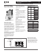
Product Description
The Cutler-Hammer
®
Intelligent Tech-
nologies (IT). Ethernet Modbus
Adapter (D77D-EMA) from Eaton’s
electrical business has greatly
increased the functionality of Cutler-
Hammer IT. communicating products,
allowing monitoring and control for IT.
I/O and IT. motor control devices. The
adapter concentrates all data from
these devices into a single Modbus
node.
The Modbus Adapter supports not
only Modbus TCP but also Modbus
serial (ASCII and RTU) as a slave
device. This combination of the two
physical layers provides for ultimate
functionality when connecting to a
Modbus system. A unique attribute of
the D77D-EMA is that it supports Mod-
bus serial Pass-Through. In this mode
a customer can connect Modbus serial
devices to one of the channels and
monitor and control them over
Modbus TCP.
To simplify the configuration of the
D77D-EMA, a simple auto-configure
button press sets the system up for
default operation. This automatically
configures the Modbus registers to the
I/O system devices.
Application Description
In a typical Modbus Adapter applica-
tion, the D77D-EMA connects directly
to Modbus, and resides in a system
with IT. I/O and other communicating
motor controls. The data from these
IT. devices is assembled into input and
output registers before being pre-
sented to Modbus.
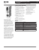
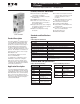
Cat. No. D77D-EMA
Features, Functions and Benefits
■ Communication to Modbus
consuming one address
■ Supports Boot P and static IP
addressing
■ 10/100 BaseT Connection
■ RS-485 Modbus slave serial
connection
■ Supports Serial Modbus Pass-
Through over Modbus TCP
■ Provides for control of all IT. com-
municating devices connected to
the gateway
■ Manually set to address and baud
rate for serial Modbus; configura-
tion using a software application is
not required for normal operation
■ Single button press auto configures
the gateway, setting up the system
for default operation
■ Advanced configuration using CH
Studio
■ Provides for backplane and inter-
connect cable connections to I/O
modules and motor control
products
■ Two independent ports for Plug-
and-Play connection to I/O
■ Powered from backplane
■ Isolated from Modbus
■ Status LEDs for Modbus and
module health
■ Provides for configuration of I/O
devices over Modbus TCP
■ Small package size
■ DIN rail mountable
Standards and Certifications
Approvals
Table 86. Approvals/Certifications
Technical Data and Specifications
Table 87. Environmental Ratings Table 88. Modbus Specifications
Description Specification
Electrical/EMC
ESD Immunity (IEC 61000-4-2) ± 8 kV air, ± 4 kV contact
Radiated Immunity (IEC 61000-4-3) 10V/m 80 – 1,000 MHz, 80% amplitude modulation @ 1 kHz
Fast Transient (IEC 61000-4-4) ± 2 kV supply and control, ± 1 kV communications
Surge (IEC 61000-4-5) ± 1 kV line-to-ground, ± 2 kV line-to-line
RF Conducted (IEC 61000-4-6) 10V, .15 – 80 MHz
Magnetic Field (IEC 61000-4-8) 30A/m, 50 Hz
Other Approvals
Ingress Protection Code IP20
Radiated and Conducted Emissions EN 5011 Class A
Agency Certifications UL 508, CUL (CSA C22.2 No. 14), CE (Low Voltage Directive),
Modbus Conformance Tested
Description Specification
Transportation/Storage
Temperature -58° – 176°F (-50° – 80°C)
Humidity 5 – 95% non-condensing
Operating
Temperature -13° –149 °F (-25° – 65°C)
Humidity 5 – 95% non-condensing
Altitude Above 6,600 ft. (2,000m)
consult factory
Shock
(IEC 68-2-27)
15G any direction for
11 mS
Vibration
(IEC 68-2-6)
5 – 150 Hz, 5G .7 mm
maximum peak-to-peak
Pollution Degree 2
Description Specification
Connections 10/100 BaseT
RS-485
I/O Size 1024 Registers Input
1024 Registers Output
Baud Ethernet 10 Megabit
Serial 1200 to 115.2K baud
Addressing Ethernet – Boot P or Static IP
Serial – DIP Switch 1 – 255
Channels 2 Independent
Channels