
Technical data


April 2008
16-22
For more information visit: www.eaton.com PG03300001E
Accessories & Modification Codes
16
16
16
16
16
16
16
16
16
16
16
16
16
16
16
16
16
16
16
16
16
16
16
16
16
16
16
16
16
16
Accessories
A200 NEMA
Replacement Auxiliary Contacts
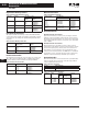
Table 16-70. Replacement Auxiliary Contacts
Extra Auxiliary Contact Kits
All starters include an auxiliary contact with 1NO and 1NC
contact. These kits include an auxiliary contact with contacts
as shown, plus operating arm and mounting bracket when
required.
Table 16-71. Extra Auxiliary Contact Kits
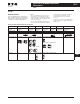
Size 7 and larger use DC coils as standard.
DC Coil Conversion Kits
Kits listed below include all necessary parts to convert from
AC to DC control including the DC coil with built-in diode,
rectifier, auxiliary interlock and all mounting hardware.
Table 16-72. DC Coil Conversion Kits
Mechanical Interlocks
Table 16-73. Mechanical Interlocks
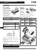
Overload Protection
Overload Protection Size 5 Starters
Type B overload relay is a three-pole, block type, thermal
ambient compensated device with manual reset mounted
integrally. Current transformers are enclosed in a protective
case and integrally mounted to save panel space. Standard
ratio is 300:5.
Overload Protection Size 6 Starters
Overload protection assembly consists of three current
transformers, Type B three-pole block overload relay and an
optional interposing relay. These parts are mounted on a
panel which connects directly to the load terminal of the
contactor. Current transformers are 600:5 ratio as standard.
If automatic reset is required, the Type A, three-pole block,
ambient compensated relay is available upon request.
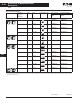
Overload Relay Kits
Each kit includes three current transformers (standard ratio)
and one Type B, three-pole block overload relay, ambient
compensated with manual reset.
Table 16-74. Overload Relay Kits
Table 16-75. Replacement Terminal Lugs
All mounting hardware is included in kit.
Contactor
Size
Contact
Arrangement
Aux. Elect. Contact
Catalog
Number
Style
Number
5, 6 1NO + 1NC
2NO
2NC
J11
J20
J02
9084A17G01
9084A17G02
9084A17G03
7, 8 1NO
1NC
—
—
578D461G01
578D461G03
9 1NO + 1NC
2NO
2NC
—
—
—
843D943G04
843D943G05
843D943G06
Contactor Size Contact
Arrangement
Style
Number
5, 6 1NO + 1NC
2NO
2NC
3463D94G18
3463D94G04
3463D94G19
7, 8
2NO
1NO
818D498G06
818D498G04
Size Voltage Kit Style Number
5 110-120
220-240
440-480
7864A28G01
7864A28G02
7864A28G03
6 110-120
220-240
440-480
7864A29G01
7864A29G02
7864A29G03
Contactor Sizes Style Numbers
Horizontal Vertical
3, 4 and 5
5 and 5
5 and 6
6 and 6
6 and 7, 8
2050A11G75
2050A11G25
2050A11G27
2050A11G26
—
2050A11G65
2050A11G15
2050A11G17
2050A11G16
2050A11G55
7, 8 and 7, 8
7, 8 and 9
9 and 9
No (Rear Conn.)
No (Rear Conn.)
No (Rear Conn.)
567D624G01
9944D56G06
9944D56G01
Kit Size Kit Part Number
5
6
2057A34G01
6379D80G10
Contactor
Size
Cable
Size
Terminals Kit Style
Number
Qty.
in Kit
Qty. Req’d.
per Pole
5
6
7
8
1-500 MCM
2-500 MCM
4-500 MCM
4-500 MCM
6
6
12
12
2
2
4
4
2119A76G01
7858A96G01
7858A96G02
7858A96G03