
Technical data


April 2008
PG03300001E For more information visit: www.eaton.com
16-17
Accessories & Modification Codes
16
16
16
16
16
16
16
16
16
16
16
16
16
16
16
16
16
16
16
16
16
16
16
16
16
16
16
16
16
16
Accessories
Advantage NEMA
Reversing and 2-Speed
Pushbutton Modules
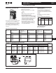
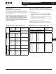
Figure 16-12. Reversing and 2-Speed
Pushbutton Module
ACM Specifications
■ Input supply requirements: 120V AC
(supplied by the Advantage motor
controller)
■ Max. distance from Advantage
motor controller: 6 ft. (1.83m)
■ Operating frequency: 50 or 60 Hz
■ Operating temperature: -20° to 70°C
■ Storage temperature: -20° to 85°C
■ Humidity: 0 to 95%, non-condensing
■ Remote input wire size: 18 – 14 AWG
■ Maximum distance between remote
pushbuttons and ACM: 200 ft.
(60.9m)
■ Cutout dimensions: 2.25 x 3.5 inches
(57.2 x 88.9 mm) (see above). The
cutout can be made using a Greenlee
rectangular punch #600710
■ Enclosure type: Type 1 or 12, when
properly installed
RES
Reset
Run Fwd
Run Rev
Off
OL Alarm
Trip
OL Trip
Status Only
RES
Reset
REVFWD
STOP
Run Fwd
Run Rev
Off
OL Alarm
Trip
OL Trip
START/STOP
Control
RES
Reset
REV
AUTO
OFF
STOP
HAND
FWD
Run Fwd
Run Rev
Off
OL Alarm
Trip
OL Trip
FWD/REV/OFF/
AUTO Control
3.5
(88.9)
2.25 (57.2)
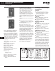
Status Only
■ 5 LEDs which indicate that the
motor is OFF, running forward
(FAST), running reverse (SLOW),
tripped or in alarm mode
■ Includes RESET button
FORWARD (FAST)/REVERSE (SLOW)/STOP
■ Pushbuttons control whether motor
is running forward (FAST), running
reverse (SLOW) or stopped
■ Includes all features of Status Only
module
FWD/REV/OFF/AUTO
■ In AUTO mode, motor is running
forward (FAST), running reverse
(SLOW) or OFF in response to a
remote signal
■ All features of FORWARD/REVERSE/
STOP module
Note: For 2-speed modules, FAST replaces
FWD and SLOW replaces REV.
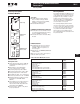
Metering Module
The Advantage Metering Module mon-
itors status of a motor along with any
of the pushbutton modules. It may be
plugged into the pushbutton control
module, and communicates to the
starter through it, or plugged directly
into the starter when a pushbutton
control module is not used.
The four digit display will show the
current in each phase, control voltage
or cause of trip. The STEP button may
be pressed to step through these val-
ues, and the five LEDs will indicate
which value is being displayed. It is
also equipped with a reset button and
Trip Lockout LED.
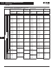
Table 16-56. Control Modules/Accessories
The WPBFV5 and WPBFV7 are DeviceNet
®
only. They can only be used when an active network is
connected.
Description Catalog
Number
Full Voltage
Status Only with Reset
START/STOP
START/STOP/HOA
ON/OFF/AUTO
LOCAL/OFF/REMOTE with Lockable ACM
LOCAL/OFF/REMOTE with Network Health
WPBFV1
WPBFV2
WPBFV3
WPBFV4
WPBFV5
WPBFV7
Reversing
Status Only with Reset
FWD/REV/STOP
FWD/REV/STOP/HOA
WPBR1
WPBR2
WPBR3
2-Speed
Status Only with Reset
FAST/SLOW/STOP
FAST/SLOW/STOP/HOA
WPB2S1
WPB2S2
WPB2S3
Reduced Voltage
Status Only with Reset
START/STOP
START/STOP/HOA
ON/OFF/AUTO
WPBRV1
WPBRV2
WPBRV3
WPBRV4
Metering Module
10 ft. Interconnect Cable (3m)
6 ft. Interconnect Cable (1.8m)
3 ft. Interconnect Cable (.9m)
1 ft. Interconnect Jumper (.3m)
WMETER
WACM10
WACM6
WACM3
WACM1