
User's Manual


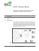


Table Of Contents
- EkaNet™ Hardware Manual
- Table of Contents
- List of Figures
- 1. Introduction
- 2. ECR-2400 Node Hardware
- 3. Elster A3/Alpha Plus Node Hardware
- 4. RESI-MON Node Hardware
- 5. EkaNet Pulse Node Hardware
- 6. Gateway Hardware

List of Figures
EkaNet Hardware Manual 10156-07
Eka Proprietary and Confidential
List of Figures
Figure 1.1: The Architecture of the EkaNet Wireless Mesh Network System ............ 1 - 1
Figure 2.1: ECR-2400 Node ....................................................................................... 2 - 3
Figure 2.2: ECR-2400 Node Layout ........................................................................... 2 - 4
Figure 2.3: Eka Node Placement within a ECR-2400 Meter ...................................... 2 - 5
Figure 3.1: Elster A3/Alpha Plus Node - Top View .................................................... 3 - 3
Figure 3.2: Elster A3/Alpha Plus Node - Side View ................................................... 3 - 3
Figure 3.3: Elster A3/Alpha Plus Node Layout ........................................................... 3 - 4
Figure 3.4: Eka Node Placement within an Alpha Meter ............................................ 3 - 5
Figure 4.1: RESI-MON Node ..................................................................................... 4 - 2
Figure 4.2: RESI-MON Node Layout .......................................................................... 4 - 3
Figure 5.1: Layout of EkaNet Pulse Node for Indoor Installations ............................. 5 - 3
Figure 5.2: EkaNet Indoor Wireless Pulse Node - Cover Removed .......................... 5 - 4
Figure 5.3: Layout of EkaNet Pulse Node for Outdoor Installations ........................... 5 - 5
Figure 5.4: EkaNet Outdoor Wireless Pulse Node - Cover Removed ........................ 5 - 6
Figure 6.1: Gateway Maintenance IP Configuration .................................................. 6 - 2
Figure 6.2: Gateway Maintenance User Configuration .............................................. 6 - 3
Figure 6.3: Successful Update to User Information ................................................... 6 - 4
Figure 6.4: Gateway Maintenance NTP Configuration ............................................... 6 - 5
Figure 6.5: Indoor Gateway ........................................................................................ 6 - 6
Figure 6.6: Indoor Gateway - Power Connection ....................................................... 6 - 7
Figure 6.7: Indoor Gateway - Cover Removed .......................................................... 6 - 7
Figure 6.8: Weather Proof Outdoor EkaNet Gateway - Closed ................................. 6 - 8
Figure 6.9: Weather-Proof Outdoor Gateway - Latches ............................................. 6 - 9
Figure 6.10: Internal Components of an Outdoor Gateway ....................................... 6 - 10
Figure 6.11: Power Input Terminals on an Outdoor Gateway .................................... 6 - 11