
Network Card User Manual


MODBUS REGISTERS
EATON Power Xpert
®
Gateway Series 1000 Card User’s Guide S 164201670 Rev 1
64
Breaker Data and Alarms
This section contains:
S Names of breaker parameters along with the register numbers for
Breaker #1
S Instructions for calculating the register numbers for other breakers
S Breaker alarms
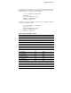
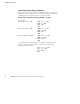
Breaker #1 Data Registers (FC 04)
To specify a specific breaker, use a Unit ID for breaker data along with
the register number for the specific breaker.
For example, “Watts in Phase A” is register 1055 for Breaker #1. This
statement is true for any panel. To specify a specific panel for breaker
data, use the panel’s Unit ID in the Modbus program. For Panel #6
(Unit ID 23), the Modbus program would be set as follows:
IP: <IP address of PDU/RPP>
Unit ID: 23
Starting Register: 1055
Number of registers: 2
Function code: 04
The Modbus program would return a value of the watts in Phase A f or
Breaker #1 in Panel #6 of the PDU/RPP at the specified IP address.
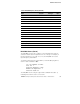
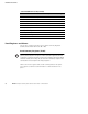
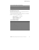
Table 7. Breaker #1 Data Registers (FC 04)
Name Register Data Type Bytes
Display Name 1000 STRING 64
Number of Phases 1032 UINT 2
Breaker Rating 1033 UINT 4
Breaker Warning 1035 UINT 2
Breaker Overload 1036 UINT 2
AC Current Phase A 1037 FLOAT 4
AC Current Phase B 1039 FLOAT 4
AC Current Phase C 1041 FLOAT 4
AC MAX Current Phase A 1043 FLOAT 4
AC MAX Current Phase B 1045 FLOAT 4