Steering Catalog Steering Control Units Torque Generators Steering Columns
Literature Referenced in this Catalog: • Eaton Technical Bulletin 3-401 • Eaton Flow Divider Catalog E-VLFL-MC001-E • Eaton Relief Valve Catalog 11-510 • Eaton Gear Pumps Series 26 Model 26000 Catalog 11-609 • Eaton Char-Lynn Low Speed High Torque Motors Catalog E-MOLO-MC001-E2 • Vickers® Screw in Cartridge Values Catalog V-VLOV-MC001-E2 • Vickers® Proportional Valves Catalog 539 • Vickers Solenoid Operated Directional Valves Catalog GB-C-2015 2 EATON Char-Lynn Steering Catalog C-STOV-MC001-E1 July 2006
Table of Contents Description and Technologies About Power Steering Description and Advantages . . . . . . . . . . . . . . . . . . . . . . . . . . . . . . . . . . . . . . . . . . . . . . . . . . . . . . . . . . . . . . . . . . . . . . . . . . . . . . . 4 Hydraulic Circuit Explanation . . . . . . . . . . . . . . . . . . . . . . . . . . . . . . . . . . . . . . . . . . . . . . . . . . . . . . . . . . . . . . . . . . . . . . . . . . . . 6-11 Neutral Circuits Open Center . . . . . . . . . . . . . . . . . . . .
Description and Advantages Steering Control Units Char-Lynn® The steering control unit (SCU) is fully fluid linked. This means there is no mechanical connection between the steering unit, the pump and the steering cylinders. The unit consists of a manually operated directional control servo valve and feedback meter element in a single body.
Description and Advantages Torque Generator SERIES 217, 227 Char-Lynn torque generators have been completely redesigned to meet the needs of the changing marketplace. These torque generators have served the industry well, providing: Displacement Flow Pressure 76 - 160 cm3/r 15 l/min 69 and 172 bar 4.7 - 9.
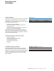
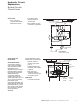
Hydraulic Circuit Explanation Neutral Circuits: Open Center and Open Center Power Beyond Open Center • Simplest, most economical system • Uses a fixed displacement pump • In neutral position pump and tank are connected • Most suitable on smaller type vehicles Open Center Power Beyond The power beyond steering control unit supplies steering and auxiliary valve functions. The power beyond unit is used on medium pressure, open center (fixed displacement pump) systems.
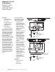
Hydraulic Circuit Explanation Neutral Circuits: Closed Center Closed Center • Uses a pressure compensated variable displacement pump • In neutral position pump and tank are disconnected • Most suitable on large construction equipment L R T P Pressure Compensated Pump Valve Option A Closed Center System Closed Center with Neutral Bleed Neutral Bleed Feature Closed Center Steering Control Units are available with and without neutral bleed feature.
Hydraulic Circuit Explanation Neutral Circuits: Load Sensing Load Sensing Circuits Char-Lynn load sensing power steering uses conventional or load sensing power supplies to achieve load sensing steering. The use of a load sensing steering unit and a priority valve in a normal power steering circuit offers the following advantages: • Provides smooth pressure compensated steering because load variations in the steering circuit do not affect axle response or maximum steering rate.
Hydraulic Circuit Explanation Neutral Circuits: Load Sensing Load Sensing Circuits— Signal Systems Two types of load sensing signal systems are available—Dynamic and Static. Dynamic Signal—Used for more difficult applications. The dynamic signal systems offer the following benefits: Dynamic Signal— Open Center Pump • Faster steering response. • Improved cold weather start-up performance.
Hydraulic Circuit Explanation Neutral Circuits: Load Sensing Static Signal— Open Center Pump Static Signal—Used for conventional applications where response or circuit stability is not a problem. The load sensing pilot line should not exceed 2 meters [6 feet] in length.
Hydraulic Circuit Explanation Work Circuits: Non-Load Reaction and Load Reaction Non-Load Reaction A non-load reaction steering unit blocks the cylinder ports in neutral, holding the axle position whenever the operator releases the steering wheel.
Steering Units with Integral Valves Integral valves are available for the Char-Lynn steering control unit. Included are: Inlet Relief Valve, Cylinder Port Shock Valves, LS-Relief Valve, and Anti-Cavitation Valves for cylinder ports. In addition, a Manual Steering Check Valve for limited manual steering is included. The integral valves eliminate the need for a separate valve block, and provides versatility to meet any steering circuit standard.
Special Features and Application Manual Steering Description Use of Graph The steering control unit can provide steering flow when the pump or engine fails. It will pump oil through the meter (gerotor) as the operator applies input or torque to the steering wheel which provides limited manual steering. 1. Determine steering work port pressure required to preform the desired steering maneuver from vehicle test data. This defines the approximate manual steering pressure level required.
Special Features and Application 2-Speed Description Eaton’s 2-Speed technology offers two operatorselectable metered modes at any time, with the touch of a button or the flip of a switch, and provides the operator flexibility to significantly improve the overall steering experience. 2-Speed technology is available on the Series 10 Steering Control Unit (SCU). Dual Steering Modes Typically, the gerotor between the SCU housing and the shift valve is the smaller gerotor (first gerotor).
Special Features and Application Dual Displacement Description Manual steering capabilities in unpowered mode The dual displacement steering control unit allows manufacturers of off road vehicles to retain manual steering capabilities while reducing the number of components in their system. By using two displacements in one unit we offer a better solution to manually steer a vehicle in an unpowered mode without the need of a back-up power system— resulting in a more economical machine.
Eaton Patented Technologies Q-Amp (Flow Amplification) for Load Sensing Circuits Description Q-Amp steering units have built in variable orifices that provide flow directly to the cylinder without going through the gerotor section. The orifices do not open until after the gerotor begins to rotate and then gradually open until the desired flow is achieved which is proportional to the flow going through the gerotor. A typical Q-Amp unit has a ratio of 1.6 : 1 which means the flow of the cylinder is 1.
Eaton Patented Technologies Q-Amp (Flow Amplification) for Load Sensing Circuits Applications Articulated vehicles such as wheel loaders, log skidders, scrapers, trucks, and similar vehicles can benefit from this feature. Variable Ratio • Wheel Loaders While roading, a slow movement of the steering wheel (input speed), will not overcorrect steering. Increasing input speed will produce the additional steering flow required to quickly change the vehicle’s direction.
Eaton Patented Technologies Wide Angle Benefits 60 RPM • Minimizes jerking motion on medium and large articulated vehicles. Flow ard • Jerk reducing valves and accumulators can be eliminated on most vehicles. 125 ms nd Steering units with wide angle features have been developed to significantly reduce or eliminate the jerky motion of vehicles with articulated steering systems. This has been accomplished by increasing the maximum deflection of the spool relative to the sleeve.
Eaton Patented Technologies Cylinder Damping Description Features Cylinder damping can help smooth the steering action of large articulated vehicles such as loaders, scrapers, and skidders. These vehicles have overhanging weight with high inertial loads. This energy is dissipated by the cylinder damping orifices which bleed a small amount of flow from the cylinder port to tank. Three levels engineered to fit your application. Cylinder Damping has 3 different levels of application.
Eaton Patented Technologies VersaSteer Description Benefits Eaton’s patented VersaSteer™ technology offers operator-selectable Metered or Quick Steering modes at any time, with the touch of a button or the flip of a switch, and provides the operator flexibility to significantly improve the overall steering experience.
Eaton Patented Technologies STC Direct Porting With the Snap-To-Connect (STC) Direct Porting option, the fitting profile is machined into the SCU housing, eliminating the need for extra STC fittings. This revolutionary and patented porting technology provides leak-proof sealing and has operating pressure capability exceeding 4500PSI (310bar). STC Direct Porting is available with Series 5 and Series 10 Steering Control Units.
Steering Control Units—Series 5 Product Description The new Series 5 steering control units (SCU) are exciting new products designed for low flow, low pressure applications.
Steering Control Units—Series 5 Model Code – Ordering Information Square Housing with Side Ports - Option 1 The following 30-digit coding system has been developed to identify all of the configuration options for the Series 5 steering control units. Use this model code to specify a unit with the desired features. All 30-digits of the code must be present when ordering. You may want to photocopy the matrix below to ensure that each number is entered in the correct box.
Steering Control Units—Series 5 Model Code – Ordering Information Round Housing with End Ports - Option 2 The following 30-digit coding system has been developed to identify all of the configuration options for the Series 5 steering control units. Use this model code to specify a unit with the desired features. All 30-digits of the code must be present when ordering. You may want to photocopy the matrix below to ensure that each number is entered in the correct box.
Steering Control Units—Series 5 Installation Drawing Option 1: Square Housing with Side Ports refer to Model Code, page 23 44,4 [1.75] Dia. Involute Spline 12 Tooth 16/32 D.P. 30° P.A. PER SPC DS-023-2 4X M10 x 1.5-6H 15,2 [.60] Min 58.37 [2.298] 29,18 48.26+0.13 [1.149] [1.900+.005] Side View 40,6 [1.60] MAX 58,37 [2.298] 38,4 [1.51]MAX 58,37 [2.298] 29,18 [1.149] 78,5 [3.09]MAX Code 35 37 39 41 43 46 48 Displacement cm3/r [in3/r] 31.5 [1.92] 39.5 [2.41] 50.8 [3.10] 63.1 [3.85] 73.8 [4.50] 100.
Steering Control Units—Series 5 Installation Drawing Option 3: Square Housing with End Ports refer to Model Code, page 24 Option 2: Round Housing with End Ports A Involute Spline 12 Tooth 16/32 D.P. 30° P.A. 44,4 [1.75] MAX 9,9 [.39] MIN 9,1 [.36] MAX 69,85±0,05 [2.750±.002] Dia. 80,5 [3.17] MAX 28,6 25,7 [1.126] MAX Dia. [1.01] MAX Dia. 59,00 [2.323] Dia. 80,5 [3.17] MAX 5,1±0.8 [.20±.03] 4 x M6 x 1.0-6H 12,2 [.48] Min. Depth 8,9 [.35] MIN 26,4±0,5 [1.04±.02] 20,3±0,5 [.80±.02] 19,8±0,5 [.78±.
Steering Control Units—Series 5 Performance Data Neutral Pressure Drop Inlet to Auxiliary bar Relief Valve Curve 11 L/min [3 GPM] Rated Round Unit [PSI] [120] 8 1 3 L/min 7 9 5 11 13 15 2000 135 1900 6 [ 80] 4 125 1800 115 1700 1600 [ 40] 2 0 0 4 [1] 7 [2] 11 [3] 105 1500 95 1400 [ 0] 15 [4] L/min [GPM] 1300 85 1200 bar 1100 75 PSI 1000 bar 19 L/Min (5 GPM) Rated Unit 14 [PSI] 65 [250] 55 900 800 [200] 700 45 600 [150] 10 [100] 6 35 0 500 0 1 0 [ 5
Steering Control Units—Series 5 Integral Column Option Integral Column Option Available in Square Housing with Side Ports, and Round Housing with End Ports 65.0 ± 0.5 [2.56 ± .02] 40 Tooth Serrated Integral Column Option (Shown on Round Housing with End Ports) 9.1 [.36] MAX 29.36 ± 0.25 [1.156 ± .010] 14.27 ± 0.25 [.562 ± .010] 17.919 [.7055] 19.2 25.7 [1.01] MAX [.755] MAX M16 x 1.5-6g Tapered 17.919mm (.7055in) diameter, .083:1 and serrated 17.5 (.688) diameter, 40 tooth, M16x1.
Steering Control Units—Series 10 Product Description Eaton’s Series 10 Steering Control Unit (SCU) facilitates hydraulic fluid flow like no other unit on the market. This highly-engineered product is the ultimate SCU for mid-range flow applications. Benefits • The new Series 10 SCU has an unprecedented, continuous pressure rating of 275 bar (4000 psi), making it ideal for heavy-duty equipment, such as construction and agricultural machinery.
Steering Control Units—Series 10 Model Code— Ordering Information The following 32-digit coding system has been developed to identify all of the configuration options for the Series 10 steering control units. Use this model code to specify a unit with the desired features. All 32-digits of the code must be present when ordering. You may want to photocopy the matrix below to ensure that each number is entered in the correct box.
Steering Control Units—Series 10 Model Code— Ordering Information— Continued Nos Feature Code Description Nos 17,18 Inlet or Load Sense Relief Valve — bar [PSI] 00 18 19 20 21 22 23 24 25 26 27 28 29 30 31 32 33 34 35 36 37 38 39 40 99 None 124 [1800] 131 [1900] 138 [2000] 145 [2100] 152 [2200] 158 [2290] 165 [2390] 172 [2490] 179 [2600] 186 [2700] 193 [2800] 200 [2900] 207 [3000] 214 [3100] 220 [3190] 227 [3290] 234 [3390] 241 [3500] 248 [3600] 255 [3700] 262 [3800] 269 [3900] 276 [4000] 136 [1970
Steering Control Units—Series 10 Model Code— Ordering Information— Continued Nos Feature Code Description 21,22,23,24 Ports and CAFA Mounting Threads (continued) 4 x G 1/2 (BSP) Straight Thread Ports G 1/4 (BSP) LS Straight Thread Port on Side 2 x M12 Mounting Threads Port Face 4 x M10 Mounting Threads Mounting Face CAGA 4 x G 1/2 (BSP) Straight Thread Ports G 1/4 (BSP) LS Straight Thread Port on Port Face 2 x M12 Mounting Threads Port Face 4 x M10 Mounting Threads Mounting Face DAAA DAHA DAJA D
Steering Control Units—Series 10 Installation Drawing PORT AND MOUNTING THREAD COMBINATIONS Port 3/4 -16 M18 x 1,5-6H STC G 1/2 (BSP) Column Mounting Thread M10 x 1,5-6H M10 x 1,5-6H M10 x 1,5-6H M10 x 1,5-6H Load Sensing* Port 7/16 - 20 M12 x 1,5-6H STC G 1/4 (BSP) Port Mounting Thread M12 x 1,75-6H M12 x 1,75-6H M12 x 1,75-6H M12 x 1,75-6H * LS side port location changes with a LSR Load Sensing Side Port 44,45/44,34 [1.750/1.746] Dia. 83,8 [3.30] Dia. Max. *Load Sensing Units Only. 8,89/8,39 [.
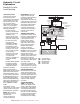
Steering Control Units—Series 10 Sectional Drawing and Integral Valves AA BB CC AA Inlet Check Valve DD EE BB FF Inlet Load Relief or Sense Valve Relief Valve CC Internal Check Valve for Limited Manual Steering DD Cylinder Port Shock Valves EE Anti-Cavitation Valves for Cylinder Ports FF 34 EATON Char-Lynn Steering Catalog C-STOV-MC001-E1 July 2006
Steering Control Units—Series 10 Performance Data Cylinder Relief Valve Inlet Relief Valve Pressure Drop versus Flow Pressure Drop versus Flow 4 6 8 Flow l/min 10 12 14 16 18 0 350 Flow l/min 20 10 30 40 220 [5000] [3000] 190 280 [4000] bar [PSI] 210 [3000] [2500] [PSI] [2000] 160 bar 130 [1500] 100 140 [2000] 1 2 3 Flow GPM Legend* P1 (23) 4 5 P2 (27) P3 (30) [1000] 70 0 5 10 Flow GPM P4 (34) Legend** *The examples above are 4 of 27 pressure settings shown in P
Steering Control Units— Series 10 Dual Displacement Installation Drawing PORT AND MOUNTING THREAD COMBINATIONS Port Column Mounting Thread M10 x 1,5-6H M10 x 1,5-6H M10 x 1,5-6H M10 x 1,5-6H 3/4 -16 M18 x 1,5-6H STC** G 1/2 (BSP) 56,1 [2.21]* 47,8 [1.88] *Load Sensing Units Only. **See Page 32 (lower right). A B 37,08/36,32 [1.460/1.430] 63,12/62,62 [2.485/2.465] 56,13/55,37 [2.210/2.180] Load Sensing/Power Beyond Side Port 21,1 [.83] 38,61/38,41 [1.52/1.480] C D Gerotor 1 48,8 [1.92] Max.
Steering Control Units— Series 20 Product Description The Series 20 steering control unit continues Eaton’s tradition of innovative design and high quality that began with the first fluid linked power steering system. You can count on this steering unit to provide the same smooth, predictable steering as the Char-Lynn steering units that provide dependable, trouble-free steering on applications around the world. • Provides much smoother steering function by minimizing jerky motion on articulated vehicles.
Steering Control Units—Series 20 Model Code – Ordering Information The following 29-digit coding system has been developed to identify all of the configuration options for the Series 20 steering control units. Use this model code to specify a unit with the desired features. All 29-digits of the code must be present when ordering. You may want to photocopy the matrix below to ensure that each number is entered in the correct box.
Steering Control Units—Series 20 Model Code— Ordering Information— Continued Nos Feature 16,17 Cylinder Relief Valve Setting Code 00 6J 6V 76 7G **Cylinder Relief 7T Setting recommen84 dation is 870 PSI (60 bar) above steering 8E 8R inlet/load sense 92 pressure.
Steering Control Units—Series 20 Installation Drawing C B 9,7 [.38] Min. 4,8 [.19] Min. A 8,4 [.33] Max. 3,68/3,43 [.145/.135] E* 19,6 [.77] D 25,7 [1.01] Max. See Catalog 11-872 for Column Details. 58,37 [2.298] (2) 29,18 [1.149] (2) 44,40 [1.748] 12 Tooth Involute Spline 16/32 D.P. 30° P.A. 13,58 [.535] Deep M10 x 1,5-6H 16,2 [.60] (4) 76,7 [3.02] Mounting Surface 48,13 [1.895] 26,16 [1.030] Left Right 107,4 [4.23] Max. L 46,7 [1.84] Load Sensing Port 48,51 [1.910] RP 90,9 [3.58] Max.
Steering Control Units—Series 20 Installation Drawing (Load Sense Relief Option) Load Sense Relief Valve Left 50,5/49,5 [1.99/1.95] Tank Right 52,8 [2.08] Max Pressure Load Sense Port* • 7/16-20 UNF-2B (SAE) O-ring Port • G 1/4 (BSP) Straight Thread Port • M12 x 1,5 -6H (Metric) O-ring Port *Load sense port on port face (is only available on units with load sense relief valve).
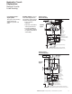
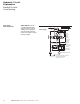
Steering Control Units—Series 20 Sectional Drawing and Integral Valves Load Sensing Port Inlet Check Valve (with Q-Amp Option) Pressure Ports (4) Inlet Check Valve (Side) Load Sensing Port* Load Sense Relief Valve *Load Sense Port on Port Face Available with Load Sense Relief Option Only Cylinder Relief Valves (2) (Standard) or Anti-Cavitation Valves (2) Shaft Bearing Seal Race (3 piece) Centering Spring (High Capacity) Sleeve Spool Gerotor Cap Screw Dust Seal Housing 42 Bearing, Needle Pin B
Steering Control Units—Series 20 Performance Data Cylinder Relief Valve Pressure Drop versus Flow 4 6 Flow l/min 10 12 8 14 16 18 350 [5000] 280 [4000] bar [PSI] 210 [3000] 140 [2000] 1 2 Legend (Code) 3 Flow GPM P1 P2 (4Z) (5S) 4 5 P3 (6J) P4 (7B) Input Torque 32 28 24 20 16 lb-in 12 8 4 0 3 2 Nm 1 0 0 10 20 30 Standard Torque 40 50 60 70 80 90 100 Percent Deflection Low Torque EATON Char-Lynn Steering Catalog C-STOV-MC001-E1 July 2006 43
Steering Control Units—Series 25 Product Description The Series 25 SCU includes two patented designs (Balanced Architecture and Wide Angle) that make it even more responsive, reliable and cost effective.
Steering Control Units—Series 25 Model Code – Ordering Information The following 29-digit coding system has been developed to identify all of the configuration options for the Series 25 steering control units. Use this model code to specify a unit with the desired features. All 29 digits of the code must be present when ordering. You may want to photocopy the matrix below to ensure that each number is entered in the correct box.
Steering Control Units—Series 25 Installation Drawing 63,5 [2.5] 3,63/1,85 [.143/.073] Right 8,8 [.35] Min. 31,8 [1.25] Left 108,8 [4.28] Dia. Max. 134,2 [5.28] Max. 44,45/44,43 [1.750/1.746] Dia. Tank Pressure 37,4 [1.47] 1 1/16 UN O-ring Port (4) 63,5 [2.5] 71,4 [2.81] Max. 4 25°/27° 89,7 [3.53] 5,4 [.21] 6,3 138,5 [.25]* [5.45] Max. 44°/46° 89,7 [3.53] Max. 34°/36°* 3/8 -16 UNC x 15,2 [.60] Deep on 82,5 [3.25] Dia. Bolt Circle 59,2 [2.33] Max.* 12 Tooth Involute Spline 16/32 D.P. 30° P.A.
Steering Control Units—Series 25 Installation Drawing with Cylinder Relief, Anti-Cavitation 3,63/1.42 [.143/.096] Right 8,8 [.35] Min. Left 108,8 [4.28] Dia. Max. 63,5 [2.5] 31,8 [1.25] 140,0 [5.51] Max. 44,45/44,43 [1.750/1.746] Dia. Tank 37,4 [1.47] 96,3 [3.79] Max. (4) 89,7 [3.53] 25°/27° 5,4 [.21] Pressure 1 1/16 UN O-ring Port (4) 63,5 [2.50] 70,4 [2.77] Max (4) 6,3 165,9 [.25]* [6.53] Max. 44°/46° 89,7 [3.53] Max. 73,7 [2.90] Max. 34°/36°* 3/8 -16 UNC x 15,2 [.60] Deep on 82,5 [3.
Steering Control Units—Series 25 Performance Data Neutral Pressure Drop - Open Center Fluid Viscosity 25 cSt [120 SUS] Average Pressure Drop at Full Valve Deflection 75 60 45 [1000] 14 [200] [ 800] 12 10 [160] bar [ 600] 30 [ 400] bar [PSI] 15 38 [10] 0 75 [20] l/min [GPM] 114 [30] [ 151 [40] 2 Nm 1 10 20 30 Low Torque Wide Angle [ 0] 0 0 75 [20] 38 [10] 114 [30] l/min [GPM] 3 0 [ 40] 2 0] Input Torque 0 [ 80] 4 [ 200] 0 [PSI] [120] 8 6 40 50 60 70 80 90 100 Percen
Steering Control Units—Series 40 Product Description The Series 40 steering control unit includes two patented designs that make it even more responsive, reliable and cost effective. Benefits • Symmetrical valving provides passageways and valving that are equal in both directions and pressure areas that are staged for minimum leakage. This gives balance, precise servo response and uniform steering action in both directions.
Steering Control Units—Series 40 Model Code – Ordering Information The following 29-digit coding system has been developed to identify all of the configuration options for the Series 40 steering control units. Use this model code to specify a unit with the desired features. All 29 digits of the code must be present when ordering. You may want to photocopy the matrix below to ensure that each number is entered in the correct box.
Steering Control Units—Series 40 Installation Drawing 67,5 [2.66] 12 Tooth Involute Spline 16/32 D.P. 30° P.A. 15,2 [.60] Min. Deep 12,9 [.51] 44°/46° 40,7 [1.60] 9,4 [.37] Min. Depth (7,1 [.28] Max. Mating Spline Depth) 7,4/4,8 [.30/.20] Spline 9,4 [.37] Min. 8,9 [.35] Max. 1,85/3,63 [.073/.143] 127,0/126,4 [5.00/4.98] Dia. Left Right 134,2 [5.28] Max. L 63,5 [2.5] R 81,3 [3.20] 66,3* [2.61] Max. P 31,8 [1.25] T 1/2 - 13 UNC x 13,4 [.53] Deep (3) 34°/36°* 1/2 - 13 UNC 13,5 [.
Steering Control Units—Series 40 Performance Data Average Pressure Drop Through Open Center Load Sensing and Closed Center at Full Valve Deflection bar [PSI] [1200] 75 [1000] 60 [ 800] 45 [ 600] 30 [ 400] 15 [ 200] 0 Open Center Neutral Pressure Drop Fluid Viscosity 25 cSt [120 SUS] 0 38 151 [20] [40] l/min [GPM] 227 [60] [ 0] [PSI] [240] bar 16 14 [200] 12 [160] 10 8 [120] 6 [ 80] 4 [ 40] 2 0 0 38 [20] 151 [40] 227 [60] [ 0] l/min [GPM] Input Torque 32 28 24 20 16 lb-in
Torque Generator Product Description Today’s market includes power steering on electric lift trucks. Char-Lynn torque generators have been designed with features that greatly improve the operator’s comfort as well as the vehicle’s performance. The increase in port surface area allows for the additional port requirement for units with the following features: Power Beyond This version has three ports: Inlet (IN), Tank (OUT), and Excess Flow (EF).
Torque Generator Product Description Continued Open Center with Case Drain Anti-Friction Needle Bearings This high pressure open center torque generator allows the exit flow from the Torque Generator to operate another function (for example reach/tilt function of a fork lift vehicle). An external case drain is needed to protect seals and to allow for adequate recentering of spool and sleeve. The flow out the case drain is internal leakage only.
Torque Generator Product Information Control End Valve, Sleeve Housing, Port/Valve Spacer Gerotor/ Geroler® Housing, Power End (with/Needle Bearing Option) Shaft, Input/ Valve, Spool Shaft, Output Centering Springs Shaft Seal Quad Seal Drive Pin Spacer Plate Static Seals (4) SPECIFICATIONS 217 SERIES—GEROTOR UNIT cm3/r [in3/r] Displacement Torque Output (at 70 bar [1000 PSI]) Recommended Flow Max. Operating Speed (at Rated Pressure and Recommended Flow) 76 [4.
Torque Generator Model Code Ordering Information The following 20-digit coding system has been developed to identify all of the configuration options for the torque generator. Use this model code to specify a torque generator with the desired features. All 20 digits of the code must be present when ordering. You may want to photocopy the matrix below to ensure that each number is entered in the correct box.
Torque Generator Conventional System Circuits Conventional System with Two Pumps Conventional System with One Pump • Extra cost of two separate circuits • Can result in insufficient steering flow when operating the auxiliary function In Torque Out Generator In Torque Out Generator Cylinder Pump Pump Valve Cylinder Pump Valve Power Beyond Torque Generator In Torque EF Generator Out • Parallel circuit • Steering has priority Relief Valve • Simple system • Single relief valve • Flow to auxiliar
Torque Generator Conventional System Circuits Load Sensing System • Steering has priority In Torque LS Generator Out • Auxiliary function can operate at higher pressure than steering rating; priority valve isolates CF side from EF side pressures.
Torque Generator Installation Drawing 217 Series (Gerotor Unit) 227 Series (Geroler® Unit) Displacement cm3/r [in3/r] 96,1 [5.86] 159,6 [9.73] 80,3 [4.90] 101,6 [6.20] 160,0 [9.64] Dimension mm [inch] A B 231,9 [9.13] 114,5 [4.51] 240,6 [9.47] 123,2 [4.85] 233,3 [9.18] 115,9 [4.56] 237,2 [9.34] 119,8 [4.72] 247,5 [9.74] 130,1 [5.12] EATON Char-Lynn Steering Catalog C-STOV-MC001-E1 July 2006 C 60,4 [2.38] 69,3 [2.73] 62,0 [2.44] 65,9 [2.59] 76,2 [3.
Torque Generator Ports 217 Series (Geroler® Unit) 227 Series (Gerotor Unit) For proper operation it is recommended that the unit be installed so no radial load or thrust load is applied to either the input or output shafts. Misalignment of shafts will cause binding. 60 EATON Char-Lynn Steering Catalog C-STOV-MC001-E1 July 2006 Displacement cm3/r [in3/r] 96,1 [5.86] 159,6 [9.73] 80,3 [4.90] 101,6 [6.20] 160,0 [9.64] Dimension mm [inch] C D 60,4 [2.38] 63,5 [2.50] 69,3 [2.73] 72,1 [2.84] 62,0 [2.
Torque Generator— 217 Series Port Block Installation Drawing Port Block with 3/8-18 Dryseal NPTF Ports EATON Char-Lynn Steering Catalog C-STOV-MC001-E1 July 2006 61
Torque Generator— 227 Series Port Block Installation Drawing 9/16-18 UNF SAE O-ring Port Displacement cm3/r [in3/r] 227 Series (Geroler® Unit) 62 EATON Char-Lynn Steering Catalog C-STOV-MC001-E1 July 2006 Dim. mm [inch] E 80,3 [4.90] 101,6 [6.20] 160,0 [9.64] 62,0 [2.44] 71,2 [2.80] 76,2 [3.
Torque Generator Performance Data Torque Generator Pressure Drop EATON Char-Lynn Steering Catalog C-STOV-MC001-E1 July 2006 63
Steering System Components Antijerk Valves Description occurs a small amount of damping flow is allowed across the turn ports. Unlike accumulators this valve will not have a negative affect on roading performance, and it is more cost effective than cushion valves. Antijerk Valves provide smoother steering on articulated vehicles, such as Wheel Loaders. This is achieved by a pressure sequence valve mounted on a block. Patent pending. (For more information see Vickers® Screw-in Cartridge Valves Cat.
Steering System Components VLC In-Line Priority Valves 60 l/min [16 GPM] Rate Flow Relief Valve Qualified for 276 bar [4000 psi] max.
Steering System Components VLE In-Line Priority Valves 150 l/min [40 GPM] Rated Flow Relief Valve Qualified for 276 bar [4000 PSI] Max.
Steering System Components VLH In-Line Priority Valves 240 l/min [63 GPM] Rated Flow Code Number DD HE LA MC NC QA UA VD VK System Pressure bar [PSI] 83 [1200] 120 [1725] 138 [2000] 150 [2175] 160 [2300] 172 [2500] 207 [3000] 230 [3325] 240 [3475] High Pressure Rated CF Pressure is 276 bar [4000 psi] Rated inlet and EF Pressure is 296 bar [4300 psi] Control Pressure - bar [PSI] / Product Number Static Dynamic Ports (5) O-ring Signal Signal Port Size 5,2 [75] 5,9 [85] P & EF 1 5/8 - 12 CF 1 5/16 - 12 60
Steering System Components VLC, VLE and VLH Priority Valves – Pressure Drop Curves VLC Series VLE Series VLH Series U.S. Patents. Re 26,338; 3,455,210 and 4,043,419 cover circuits using these priority valves. Corresponding foreign patents pending and issued.
Steering System Components Check Valves Product Description These check valves are designed specifically to withstand the rugged duty cycles of a steering system and perform their functions reliably to prevent kickback in the steering wheel. The check valve is installed directly into the pressure port of Char-Lynn steering control unit. Connection of the hose assembly is either a male 37° end or O-ring face seal (ORS). Straight 90° elbow configurations are available (see installation drawing next page).
Steering System Components Check Valves Installation Drawing D Straight D O-ring Face Seal (ORS) E C Hex. A B C Hex. E A 90° Elbow B D E B A C Hex. Configuration 37° 37° Straight ORS ORS 90° ORS 70 Product Number 608-1003 608-1004 608-1007 608-1009 608-1013 Check Valve Dimensions—mm [in.] A B C 3/4-16 3/4-16 22,61/22,10 [.89/.87] 9/16-18 3/4-16 22,61/22,10 [.89/.87] 13/16-16 3/4-16 22,61/21,10 [.89/.87] 11/16-16 3/4-16 22,61/22,10 [.89/.87] 11/16-18 3/4-16 24,13/23,62 [.95/.
Steering System Components Relief Valves Model 32107 In-Line Relief Valve–Direct Acting Cartridge T P Specifications Max. Flow Through Relief Valve 57 l/min [15 GPM] Relief Valve Setting Range 47–276 bar [675–4000 PSI] Standard Relief Valve Setting 138 bar [2000 PSI] Housing Rated Pressure 345 bar [5000 PSI] P Model 32107 In-Line Relief Valve–Pilot Operated Cartridge T P Specifications Max.
Steering System Components Columns Product Description Char-Lynn columns can be custom built to your exact specifications. The column and mounting flange is of a sturdy single weldment design. These columns have high thrust and side load capacity with low shaft tortional friction. Columns are painted with low gloss black finish and the shafts are phosphate coated and oil dipped for corrosion protection.
Steering System Components Columns Model Code, Ordering Information The following 22-digit coding system has been developed to identify all of the configuration options for steering columns. Use this model code to specify a steering column with the desired features. All 22 digits of the code must be present when ordering. You may want to photocopy the matrix below to ensure that each number is entered in the correct box.
Steering System Components Columns Jacket/Base Type Example—see model code page 73 Position 4-5 SH Standard with flat flange (No Tabs) Position 9, 10, 11 026 66,1 [2.60] (Dimension X) *Dimension X—see model code page 73 Position 9, 10, 11 (Jacket Length) SJ Standard Wall (Available on Square Series 5, Series 10, 20, 25, 40) SH Standard Wall (Available on Square Series 5, Series 10, 20, 25, 40) 6,4 [.25] Position 4-5 Dimension X* 15,2 [.60] 20,3 [.80] 44,32 [1.745] Pilot Dia. 40,6 [1.6] Dia. 40,6 [1.
Steering System Components Columns Lower End Type Example—see model code page 73 Position 6 1 12 Tooth Spline for Steering Unit 1 Position 6 6,4 [.25] Column Mounting Flange with Tabs Column Mounting Flange without Tabs Column Mounting Flange for Round Series 5 with Side or End Ports 6,1 [.24] 12 Tooth Spline to Fit Char-Lynn® Steering Control Units 3 Position 6 3/4 inch “D” Section (for Noise Isolator) Noise Isolator (Not Icluded) 18,8 [.74] Min. 107,8/105,6 [4.24/4.16] 13,54/13,44 [.533/.
Steering System Components Columns Upper Shaft End Example—see model code page 73 Position 7-8 EJ (36 Tooth Straight Serration) Not available with horn wire AJ Position 7-8 26,4 [1.04] 12,7 [.50] EJ Position 7-8 45,34 [1.785] 45,34 [1.785] 21,82 [.859] Dia. 21,8 [.86] 15,2 [.60] Note: Torque Nut to 41-54 Nm [30-40 lb-ft] For bending moment calculation when using .052 : 1 Eaton wheel product 36 Tooth Straight Serration No. 209-1007, wheel rim 21,79 [.858] Major Dia. is 22,1 [.
Steering System Components Columns Upper Shaft End Continued Example—see model code page 73 Position 7-8 YM (.050 : 1 Taper M18 x 1,5 - 6g Thread) Not available with horn wire YM Position 7-8 CL Position 7-8 Not Available with Horn 45,50 [1.790] Wire 29,36 [1.156] 50,5 [1.99] 17,92 [.705] Dia. 14,27 [ .562] Note: Torque Nut to 41-54 Nm [30-40 lb-ft] Not Available with Horn Wire or Tilt 32,0 [1.26] M18 x 1,5 - 6g Thread 52,1 [2.05] 23,2 [.913] Dia. 5 [.197] x 6,5 [.256] Woodruff Key 26,9 [1.
Steering System Components Columns Tilt Column 20 20 5 TILT POSITIONS 10 1/4" BLADE RECEPTACLE FULLY INSULATED 10 B B 4.0" .8125-20 UNEF-2A 1.04 .01 .50 .01 36 TOOTH STRAIGHT SERRATION (7/8 X 36) .858 .002 MAJOR ø .816 .002 ROOT 90 1 INCL. ROOT ANGLE .052:1 .9488 .002 ø OVER .859 .001 START ø TWO .0625 ø PINS LENGTH "A" CUSTOMER TO SPECIFY LENGTH ABOVE PIVOT (3.25" MINIMUM) 1.785 .035 RUBBER BOOT 1.50 ø "PUSH" TO RELEASE TILT LOCK 2.47 RUBBER BOOT 4.
Steering System Components Columns Horn Wire Electrical Example—see model code page 73 Position 12-16 1A045 Column with one horn wire Single Wire 01 Position 18-19 Single Wire 28,4 [1.12] 1A045 Position 12-16 9,52 [.375] Dia. Column with 1 Wire 08 Position 18-19 K or T Position 17 K — Blade Receptacle Insulated — Compatable with 6,4 [.25] Blade Per SAE J858a Tinned Bare Wire End 35,8 [1.41] 114,3 [4.50] T — SAE J928 Type I 3,96 [.156].
Steering System Components Columns and Wheel Mounting Product Information Inspect for Minimum Clearance at Assembly 1,6 mm [.06 in.] Min. Steering Wheel Hub Torque To 4,7 da Nm [35 lb-ft] Steering Column Square Series 5 and Series 10 9,5 [.375] Dia. on 3.25 [82,5] Dia. Bolt Circle (4) Must use two bolts through mounting bracket or bulkhead and two bolts through just the steering column or four bolts through mounting bracket or bulkhead. Two Bolts 3/8 -16 NC x Y + 30,5 [1.20] 30,5 [1.20] Max. 27,2 [1.
Steering System Components Columns Product Information Round Series 5 Must use three bolts minimum. Mounting Bracket or Bulkhead 59,00 [2.323] Dia. Cap Screw (1) M6 x 1,0 T L R P 41,5 [1.635] Pilot Dia. M6 x 1,0-6H 18,5 [.73] Min. Deep (4) 5,8 [.23] Cap Screw (3 or 4) M6 x (W + 12,2 [.48]) W Dim. 12,2 [.48] Max. 7,5 [.30] Min. 15,0 [.59] Series 40 Must use three bolts Into steering control unit mounting bosses opposite port face.
Steering System Components Steering Wheels and Accessories Horn Button Kit Steering Wheel Cap Nut, Hex 7 2 3 5 4 1 6 1 2 3 4 5 6 7 Weather Cover Horn Button Contact Cup Horn Button Spring Contact Cup Screw Base Plate Assembly Steering Wheel No. 209-1007 Molded black wheel with three equally spaced spokes, (relatively flat, without recessed hub) diameter 430 mm [17 inch] for column with upper shaft end AJ or MJ. Note: Steering wheel hub has tapped holes for wheel puller.
Steering System Components Steering Wheels and Accessories New Steering Wheels Horn Buttons Eaton Char-Lynn‚ offers three new steering wheels each with different features: 9900416 209-1022: 350mm [14in] diameter, 3-spoke steering wheel with horn button option. 209-1023: 362mm [15in] diameter, 3-spoke steering wheel with knob standard and optional horn button. For Char-Lynn‚ steering column with upper shaft end AJ and steering wheel 209-1022 and 209-1023.
Steering System Components Steering Wheels and Accessories This Noise Isolator is Available from Eaton— Part Number 208-1017-002 See Note Below 82,6 [3.25] Dia. See Note Below Lower End Type 3 (Ref.) Upper Shaft End EJ (Ref.) 61,0 [2.40] Note: Two screws (3/8-24 UNF x 31,8 [1.25] long — not included) are required to join isolator to mating steering columns. Torque screws to 41 Nm [360 lb-in]. Want to Make your Own Column? You Must use these Spline Specs. Lower Shaft End Major Dia. 20,40/20,24 [.803/.
Steering System Components EH Proportional Loadsensing Steer Valves Description EH proportional steer valves are commonly used for GPS steering, joystick steering, and autoguidance. This is achieved by a manifold containing a shuttle valve, a counterbalance valve, and a KDG proportional control valve.
Steering System Components Four Wheel Steer Switching Valves Description FRONT Applications Four Wheel Steer Switching Valves provide three different types of steering by energizing and de-energizing two DG4V-3 valves. DG4V-3 valves are high performance, solenoid operated directional control valves. • Two Wheel Steering: Energize Solenoid S1 L R P • Telehandlers • Sprayers • Rough terrain Cranes T S2 S1 S4 S3 • Backhoe Loaders Ordering Information 1.
Steering System Components Flow Divider Valves Model 32306 Priority Flow Divider Specifications Rated Input Flow Rated Pressure Excess Flow Controlled Flow 96,6 l/min [25 GPM] 172,4 bar [2500 PSI] Max. Pressure Drop Through Valve at Rated Input Flow 4,5 bar [65 PSI] P Model 32501 Proportional Flow Divider Specifications Rated Input Flow Rated Pressure In 113,6 l/min [30 GPM] 172,4 bar [2500 PSI] Max.
Steering System Components Brake Valve Eaton Hydraulics’ loadsensing brake valve makes power brakes an economical and efficient feature on lift trucks. While power brakes in lift trucks can aid productivity, incorporating them into lift trucks has traditionally been expensive. The need for additional flow meant extra plumbing, plus the addition of a dedicated pump or a high pressure accumulator for the brake circuit.
Steering System Components T Series Hydraulic Motors Char-Lynn T Series low speed, high torque Geroler motor developed with low speed/low leakage valving specifically for steering applications (see Catalog E-MOLO-MC001-E2 Low Speed High Torque Motor page B-4-10 Code AB, Position 11-12). Pressure Capability Continuous Intermittent Speeds Torque Continuous Intermittent 11 Displacements to 155 bar [2250 PSI] 190 bar [2750 PSI] up to 1055 RPM 440 Nm [3905 lb-in] 510 Nm [4515 lb-in] 36 cm3/r [ 2.
Sizing and Application— Ackermann Type Steering Step One: Kingpin Torque F r Minimum Effective Radius Arm 0.7 0.6 S 0.5 0.4 f 0.3 B E 0.2 V 0.1 A T =w•f Weight 0.2 0.4 0.6 0.8 1.0 1.2 E/B Typical values based on rubber tired vehicles on dry concrete. A B2 + E2 8 T = Total Kingpin Torque required to steer axle. Kingpin W = Vehicle Weight supported by the steered axle. T f = Coefficient of friction (dimensionless). Based on 0.7 as a Maximum. Determine from chart at left.
Sizing and Application Ackermann Type Steering Continued Step Two: Force Required F = T r F = Force required for the axle. T = Kingpin torque as determined in Step 1. The value calculated in Step 1 is the total torque for the axle. If the steered axle is power driven, double this value to approximate the additional dynamic loads. r = Effective radius arm about the kingpin axis at which the cylinder force is applied.
Sizing and Application Ackermann Type Steering Continued Step Three: Step Four: Selecting Steering Unit Displacement Calculating Required Pump Flow Before proceeding further, a decision must be made as to the number of steering wheel revolutions desired for the application to steer the axle from full one side to the other. Depending on vehicle usage, this will vary, normally 2 1/2 to 5 1/2 with 4 being a good typical value Displ.
Sizing and Application Articulated Type Steering Eaton’s Hydraulic Division has developed a computer program to assist articulated vehicle designers with a steering system analysis. This analysis can provide basic system sizing, pressure requirements or a complete system analysis including dynamic characteristics. This analysis is intended to be used as a guide only and is not to be used solely as the final determination of system design. Other factors and variables will have to be considered.
EATON Char-Lynn Steering Catalog C-STOV-MC001-E1 July 2006
Sizing and Application Articulated Vehicle Steering Analysis Clip out this form or photocopy when needed.
EATON Char-Lynn Steering Catalog C-STOV-MC001-E1 July 2006
Sizing and Application Articulated Vehicle Steering Analysis Clip out this form or photocopy when needed.
Eaton 14615 Lone Oak Road Eden Prairie, MN 55344 USA Tel: 952 937-9800 Fax: 952 974-7722 www.hydraulics.eaton.com Eaton 20 Rosamond Road Footscray Victoria 3011 Australia Tel: (61) 3 9319 8222 Fax: (61) 3 9318 5714 Eaton Eaton Fluid Power GmbH Dr.-Reckeweg-Str. 1 D-76532 Baden-Baden Germany Tel: +49 (0) 7221 682-0 Fax: +49 (0) 7221 682-788 © 2006 Eaton Corporation All Rights Reserved Printed in USA Document No.