
Installation Manual

©2015 EasyHeat www.easyheat.com 14183-001 Rev 0
US T. (800) 537-4732
CAN T. (800) 794-3766
6
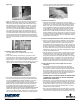
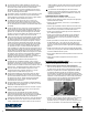
plastic clips. Place clips over the cold lead and the heating cable at
the splice and SECURE them to the oor. ENSURE THAT STAPLES
DO NOT PENETRATE THE CABLE! (Figure 2a)
(Figure 2b)
Figure 2a —2b. Securing cold lead splice
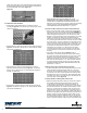
2.4 Install cable in the membrane
• Embed Heating Cable (White section) in membrane channels
according to Figure 2c. Use a roller to secure cable in place. Install
cable runs as follows:
Figure 2c. Secure cable
• Standard Spacing: Cables are spaced 3 channels apart according to
Figure 2d - this results in spacing of 3-3/4” (90mm) between cables
and provides 12 Watts/sq.ft.
Figure 2d. Standard cable spacing
• Alternate Spacing: Cables are spaced alternately 3 channels
apart and 2 channels apart according to Figure 2e - this results in
spacing of 3-3/4” (90mm) and 2-1/2” (60mm) between cables and
provides 14.5 Watts/sq.ft.
Figure 2e. Alternate cable spacing
• Dense Spacing: Cables are spaced 2 channels apart according to
Figure 2f - this results in spacing of 2-1/2” (60mm) between cables
and provides 18 Watts/sq.ft.
Figure 2f. Dense cable spacing
NOTE: HEATING CABLE MUST BE INSTALLED IN THE
MEMBERANE IN THE MANNER DESCRIBED. FAILURE TO DO
SO MAY RESULT IN IMPROPER SYSTEM OPERATION. If any
adjustment in the cable spacing is required, carefully pull out heating
cable and reposition. THE DISTANCE BETWEEN ADJACENT
CABLE RUNS MUST NOT BE LESS THAN 1 ½” (38 mm).
2.5 If “half of cable” marker does not meet at “half heated area”
• When you reach the “Half of Cable” marker, pause to evaluate the
remaining area. If the “Half of Cable” Marker appears BEFORE the
Half-of-Area-Line previously marked on the oor, there will likely be
a cable shortage at the planned end of run, the amount of which
depends on how far before the line the marker appears. For a cable
shortage, consider the low trafc areas and Border Dimension.
Cable can be conserved by avoiding placement in low trafc areas
or by increasing the border dimension. The border may be increased
to a maximum of 6”. To do this, carefully remove the cable from the
mat and increase the border dimensions, but no further than 6” (15
cm) from the wall; this will reduce cable usage. Re-install the cable
according to the method outlined in Step 2.4. Do NOT increase
cable spacing by more than 3-3/4” (90mm) as this will result in
a cold oor! Once the cable layout is complete, ensure all cable
runs are sufciently secured to prevent interference during mortar
trowelling.
• If the “Half of Cable” Marker appears AFTER the Half-of-
Heated-Area- Line previously marked on the oor, there will likely
be a cable surplus at the planned End of Run, the amount of which
depends on how far past the line the marker appears. Surplus
cable may be used up by routing it into Low Trafc Areas. You may
also reduce the cable spacing to 2-1/2” (60mm) between adjacent
runs. Both methods will help to consume the surplus cable. THE
DISTANCE BETWEEN ADJACENT CABLE RUNS MUST NOT BE
LESS THAN 1 ½” (38 mm).
2.6 Secure sensor wire, tail splice and any loose cable
• If a oor temperature sensor will be used, position the Sensor Wire
midway between two adjacent Heating Cable runs. The end of
the sensor wire should extend at least 6” (15 cm) from the Return
Loop and lay in the centre of spacing between two heating cables.
Embed the sensor wire in the membrane. After installing the cable
completely, follow step 2.3 to create housing for the tail splice and
secure the splice in place. (Figure 2b)
2.7 Verify resistance of heating cable & sensor wire
• Before proceeding with nal oor nishing, measure the resistance
of the Heating Cable and optional Sensor Wire to ensure that
no damage has occurred to either cable during installation. To
measure heating cable resistance, connect the ohm-meter leads to
the Cold Lead conductors. The resistance will be between 10 and
250 ohms. To measure sensor resistance, again connect the ohm
meter leads to the sensor wire conductors. The resistance will be
between 7 and 14 k-ohms. If the resistance of either cable does not
fall within the specied range, please contact Easy Heat toll free at
(800/537-4732) and DO NOT energize the heating cables. If each
resistance reading is within the specied range, you may be ready
to proceed with oor nishing. NOTE: Your system Installation may
require an electrical inspection at this time (prior to proceeding with