
Installation Manual

©2015 EasyHeat www.easyheat.com 14183-001 Rev 0
US T. (800) 537-4732
CAN T. (800) 794-3766
5
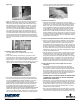
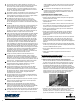
(Figure 1b).
Figure 1b. Fish hole preparation
• Fasten “Do Not Remove” tags to sh cords at the still plate holes
(Figure 1c). Install Power Supply Wiring, but do NOT energize
or connect to the heating controller until the nished ooring has
been installed. Install conduit if required (consult with your local
inspection authority). Drywall installation can now be completed
and heating cable can be installed later. Typically requires a 15
cubic inch box for single cable installations. Multiple cable sets
may require larger boxes. Consult your local electrical authority.
Determine the appropriate location and height for the Electrical
Connection Box* (ECB). Consider proximity to other outlet boxes,
ease of routing Cold Lead to the Heated Area, and accessibility to
a planned heating controller. The cold lead should enter the same
wall cavity in which the ECB is located. Consult your local electrical
authority.
Figure 1c. “Do Not Remove” tags installation
1.2 Electrical rough-in: Remodeling project
For a remodeling project, complete the electrical rough-in
as follows:
• Remove base moldings, and drywall only as required, in areas
where sh holes are to be drilled, exposing upper edge of sill plate.
Drill a horizontal ¾” (19 mm) diameter hole through the sill plate
approximately 1½” (38 mm) deep. If installation is planned for two
heating cables, a second sh hole should be drilled a minimum of 4”
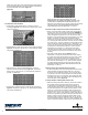
(100 mm) from the rst, but within the same cavity (Figure 1d).
Figure 1d. Fish hole preparation
• Use a chisel to completely notch wood from the sill plate above
each hole. Clear sh holes of wood chips and install cable guards
over the holes (Figure 1e). Use ECB as template to mark outline
on wall at appropriate height. Carefully cut out the minimum
possible amount of drywall to prevent the need for wall repair after
heating controller has been installed. Install a sh cord through
the sill plate, pull through the wall cavity and secure in the ECB.
ONE ADDITIONAL FISH CORD WILL BE REQUIRED IF THE
INSTALLATION WILL INCLUDE A FLOOR TEMPERATURE SENSOR.
Install Power Supply Wiring in the ECB, but do NOT energize or
connect to the heating controller. Install conduit, if required (consult
with your local electrical inspection authority).* Typically requires a
15 cubic inch box for single cable installations. Multiple cable sets
may require larger boxes. Consult your local electrical authority.
Figure 1e. Fish hole clearing
2.1 Verify size of heated area
• Conrm the cable selected will provide the correct coverage by
measuring your room oor and determining the square footage to be
heated. This is your Heated Area. Areas under cabinets or xtures
(toilets, sinks, tubs, etc.) should NOT be included. Heating cables
may be installed under tiled shower surfaces provided the cables
are embedded in a cement-based underlayment and covered by
an approved water impermeable membrane. Consult your local
electrical and/or building inspection authorities for more information.
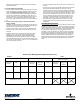
Using the heated area, supply voltage (120V or 240V) and the choice
of Standard, Alternating or Dense Heating Cable Spacing, Verify that
you have the recommended cable set for your application using the
cable selection chart on the box.
2.2 Install Uncoupling Membrane to the oor and Plan cable routing
• Ensure your uncoupling membrane is suitable for use with radiant
heating products. Install the Membrane to the oor according to its
manufacturer’s installation instructions. Mark the heated area on
the membrane using an appropriate marker. Carefully measure and
locate the mid-point of the Heated Area (NOTE: This may differ from
the linear mid-point from one end of the room to the other). This will
be a useful reference line later, as it should coincide with the “Half of
Cable Marker”. Using a heavy-tip marker, straight edge and square,
mark the ‘half of heated area line.
• Plan the cable layout on the membrane. It may be helpful to outline
the cable path on the membrane using a suitable marker. Carefully
consider the location of Low Trafc Areas. Allow sufcient space
along walls and cabinets for the heating cable Start of Run. Heating
cable should be within 1-1/2” (38 mm) of any vanity kick plate. The
Border Dimension may vary between 1-1/2” (38 mm) to 6” (15 cm)
depending on the cable coverage range and the size of your room.
Usually, it is best to start with 3” (75 mm) and adjust if required.
2.3 Pull cold lead and sensor wire into ECB; secure the Cold
Lead Splice
• It is important to properly de-coil the cable to prevent twisting.
Insert a rod (such as a broom handle) through the cable spool hub
and support on a ladder or equivalent. Pull the Cold Lead from the
spool, and using sh cords, pull it through the ¾” (19 mm) hole in
the sill plate, up through the wall cavity and into the ECB. The cable
should be pulled until the factory Cold Lead Splice on the oor is
approximately 12” (30 cm) from the sill plate hole.
WARNING: DO NOT ALLOW ANY PORTION OF HEATING CABLE
TO ENTER WALL CAVITY AREA. ALL HEATING CABLE MUST
REMAIN IN THE FLOOR/STEPS.
• Allow at least 6” (15 cm) of cold lead to project from the ECB. If you
are using a oor temperature controller use the sh cords to pull the
Sensor Wire through the sill plate hole, up the wall cavity and into
the ECB. Allow at least 6” (15 cm) of sensor wire to project from the
ECB. Temporarily secure the Sensor Wire at the oor – it will get
installed in the oor later in Step 2.6.
• Due to the larger cable diameter of the cold lead splice, cut out the
mat material under the splice to eliminate any possible interference
with the tile. Secure cold lead splice and cold lead to the oor using