
Installation Manual

©2015 EasyHeat www.easyheat.com 14183-001 Rev 0
US T. (800) 537-4732
CAN T. (800) 794-3766
4
When installing cable in oors that are routinely expected to be
wet, such as tile showers, a waterproong membrane must be
installed ABOVE the cables to keep them dry. The cables are not
rated for wet locations, and water could seep into the cable and
result in cable failure, shock hazard and/or re.
It is recommended that the circuit supplying the heating cable
have ground fault protection; this is mandatory by electrical code
for most applications in most regions. In cases where the oor
is routinely expected to be wet, such as tiled showers, a Ground
Fault Circuit Interrupter (GFCI), or equivalent, must be installed
Additionally, per US National Electrical Code, installation in some
rooms, such as bathrooms and kitchens, may require that this
product be installed on a circuit protected by a separate Ground
Fault Circuit Interrupter (GFCI). Consult your local electrical and/
or building authorities to determine the specic ground fault
requirements for your application prior to installation. If you are
unsure that your circuit has ground fault protection, consult an
electrician.
If the ground fault protection circuit trips during normal operation,
and cannot be reset, there is likely a fault in the heating cable.
No attempt should be made to re-energize the system. Under no
circumstances should the ground fault protection be bypassed –
contact EasyHeat for advice.
Do not bend the heating cable at right angles – this could damage
the electrical insulation; minimum bending radius is ¾.” (19 mm)
Do not use staples to afx cold lead, heating cables or thermostat
sensor wire, as this could puncture the heating cable resulting in
short circuit or exposed live electrical parts. Use only the cable
strapping provided with the system, and only staple according to
the instructions.
Do not place more than six consecutive/adjacent runs of heating
cable at 1 ½” (38 mm) spacing; doing so will cause the oor area
to overheat.
Only connect cables to the rated voltage – do not use higher
voltages as the increased current will cause cable to overheat.
Ensure that all electrical control devices, such as thermostats, are
properly rated for the heating cable load. Do not overload these
devices as they will overheat or otherwise fail.
Ensure that copper grounding braid material is directly connected
to electrical ground – do not cut the ground braid. If the ground
braid is not connected to ground, the heating cable will not be
grounded and may not provide the required protection against
short circuits or electrical shocks.
These instructions have been prepared for use with standard
North American building construction practices. If your building
construction differs, consult an appropriate electrical professional.
INSTALLATION PLANNING
Carefully plan your installation before beginning.
• Ensure you have selected the appropriate cable and spacing
(Standard for 12 watts/sq ft, Alternate for 15 watts/sq ft, Dense for
18 watts/sq ft).
• Ensure the power supply (120 or 240 VAC) is adequate for the
selected cable.
• Ensure that ground fault protection will be provided for the cable
– many oor warming thermostats are provided with ground fault
protection.
• Verify that the control method you have selected for the cable is
appropriate.
• Verify that the uncoupling membrane that will be installed is
appropriate and that it will not result in the heating cable being more
than ¾” (19mm) from the nished surface of the oor.
• Check that the nominal distance between the channels of the
uncoupling membrane is 1-1/4” (30 mm) on-center; if this is not the
case, adjustment in the cable spacing may be required to ensure
appropriate heat is applied to the oor.
• Check that the width of the channels in the uncoupling membrane
is 0.2” (5 mm) and that the DMC cable ts snuggly into the channel
and is sufciently secured in place.
• Clear the oor area of all debris and sharp edges prior to beginning
installation.
• Obtain appropriate permits prior to beginning installation.
• Before installing the cable, measure the resistance of the Heating
Cable and optional Sensor Wire to ensure that no damage has
occurred to either cable during installation.
• To measure heating cable resistance, connect the two ohm meter
leads to each of the Cold Lead conductors. The resistance will be
between 10 and 250 ohms.
• To measure sensor resistance, again connect the two ohm meter
leads to each of the sensor wire conductors. The resistance will be
between 7 and 14 k-ohms. If the resistance of either cable does not
fall within the specied range, please contact Easy Heat toll free at
(800-537-4732) and DO NOT energize the heating cables.
• If each resistance reading is within the specied range, you may be
ready to proceed with cable installation. We also recommend an
insulation resistance test: Connect a Mega ohms meter between
the copper grounding braid and the two conductors connected
together.
• Set the tester at 500 V (minimum) and measure the insulation
resistance. The resistance must be 10 Megohms minimum. This test
assures that the cable has not been damaged during shipment or
subsequent handling.
INSTALLATION INSTRUCTIONS
Installation of Warm Tile system is done in sequence as described
below. Follow these steps carefully.
1.1 Electrical rough-in: New construction
For new construction it is recommended that rough-in be completed
before drywall/sheetrock installation.
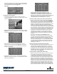
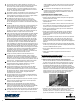
• Determine the appropriate location and height for the Electrical
Connection Box* (ECB). Consider proximity to other outlet boxes,
ease of routing Cold Lead to the Heated Area, and accessibility of
the heating controller during normal use. Typically the cold lead
enters the same wall cavity in which the ECB is located. Install the
ECB, adjusting box projection to suit expected wall covering (Figure
1a).
Figure 1a. ECB installation
• Prepare a sh hole, rst by drilling a horizontal ¾” (19 mm) diameter
hole through the sill plate approximately 1½” (38 mm) deep. Drill a
second ¾” (19 mm) diameter hole vertically through the sill plate
connecting to the rst hole. If installation will require two cables,
a second sh hole should be drilled a minimum of 4” from the
rst but preferably within the same wall cavity. Clear sh holes of
wood chips and install cable guards over holes (these are usually
required to be sourced separately) over the holes. Install a sh cord
through the sill plate, pull through the wall cavity, and secure in the
ECB. ONE ADDITIONAL FISH CORD WILL BE REQUIRED IF THE
INSTALLATION WILL INCLUDE A FLOOR TEMPERATURE SENSOR