
Install Instructions

MSC‑1 Installation & Operating Instructions 5
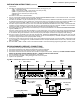
Zone Assignment
The MSC‑1 uses the concept of a zone system to most
efficiently control snow/ice melting equipment. The term
“zone” means an area (either surface area or roof/gutter
area, or some combination of both) heated by a specific
set of snow/ice melting equipment that is controlled in a
common manner. The MSC‑1 allows for up to three zones,
and each zone can have multiple moisture sensors for, say,
roof/gutter, aerial and/or surface snow/ice detection. If any
one of the sensors detects moisture, the heating equipment
may be energized. The moisture sensor in the zone should be,
generally, “surrounded” by the heating equipment to ensure
that the heating equipment is only energized when there is
indeed snow/ice present in the zone.
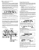
Zones can be used to represent different areas; for example
a parking ramp area could be one zone while roof/gutter de‑
icing on the same building could be another zone. Similarly, two
sidewalks on different sides of the same building (possibly one
on the north side and one on the south side) could represent
two separate zones. The perimeter of a football stadium could
be split into three separate zones to reflect different weather
conditions on different sides of the building.
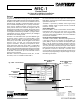
OPERATION
The MSC‑1 is a programmable controller, capable of
controlling three separate snow/ ice melting zones. A control
relay for each zone is included in the MSC‑1 to operate a
contactor for each zone to energize the snow/ice melting
equipment. There are two operating mode selections possible
with the MSC‑1:
Mode 1 – Independent
In this mode each snow/ice melting zone is controlled
independently. Mode 1 allows all 3 zones to be energized
simultaneously. This mode is best used where circuit loading
is not a concern (e.g. adequate circuit ampacity is available
to operate the entire snow/ice melting load simultaneously).
Mode 2 – Priority
In this mode each zone is controlled on a priority basis,
with the most critical zone (always Zone 1) being melted
first, followed then by the less critical zones. Mode 2 allows
only 1 of the zones to be energized at a time. This mode is
best used where circuit loading is a concern. A slight delay
is provided when switching power between zones to ensure
circuits are not overloaded. Set‑up in Mode 2 must be done
either with Zones 1 & 2, (with Zone 3 not being used), or
Zones 1, 2 & 3. Operation is sequential, beginning with Zone
1. When Zone 1 is melted, the MSC‑1 de‑energizes it and
then energizes Zone 2. However if snow/ice is detected on
Zone 1, Zone 2 is de‑energized and Zone 1 re‑energized.
Similar logic applies for Zone 2 & 3; i.e. the lower numbered
zone always takes priority.
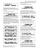
The Priority mode available in the MSC‑1 can reduce circuit
loading by splitting up a large snow melting area into separate,
smaller zones. For example, if a large area would require 90
Amps of current, this could be split into two separate zones of,
say, 50 Amps in one zone and 40 Amps in the other. Then, by
programming the MSC‑1 in the Priority Mode, only one zone
will be enabled at any one time, resulting in a maximum circuit
loading of 50 Amps. Similarly, the area could be split into three
zones of, say 25, 35 and 30 Amps; in this case circuit loading
would be 35 Amps maximum. It should be further noted that
when in Priority mode, the MSC‑1 always gives priority to Zone
1; when Zone 1 is completely melted, then Zone 2 is enabled
until melted, and then, finally Zone 3; i.e. Zone 1 always has
higher priority over Zone 2, which has higher priority over
Zone 3. Further, if snow/ice is detected in a zone with higher
priority, then operation reverts to the zone with higher priority.
For example, if melting has been completed in Zone 1, and
Zone 2 has thus been enabled, then if snow/ice is detected
in Zone 1, operation in Zone 2 will be suspended, and Zone
1 will be re‑enabled until melting is again complete, at which
time melting in Zone 2 will recommence.
It is also important to give consideration to the assignment
of zones; usually, high traffic areas will be given priority, with
lower traffic areas given lower priority. Zones can be easily
reassigned at the wiring terminals of the MSC‑1.
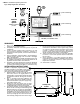
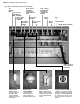
SYSTEM CHECK
Before you power up, confirm:
• Allthesensors,relaycoilsandthepowersupply
are connected to the proper terminal blocks.
• Onlyunshielded(shieldedforMSP-1)cablewasusedtoextend
the sensors, with a maximum size of 18AWG.
• Thepolarityofthepowersupplyisappropriate,120VAC.
• Youhaveconnectedtheoutputterminalstoarelay
or contactor coil, NOT DIRECTLY TO THE LOAD
After powering up, you should see:
• Thedisplaylitandreadingthetemperatureintheareaofthe
TS‑1.
• ThesmallgreenLED'snexttotheconnectedterminal
blocks are lit (no LED for the TS‑1 block).
• Thesensorlights(fortheactivatedzonesensors)onthefront
panel will be lit.
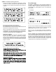
To cycle system and check sensor operation:
1. Submerge the TS‑1 in a litre of water and crushed ice.
2. After 20 minutes, confrim the display reads 32F (0C).
3. Put a drop of water on each sensor surface*, the Power
Relay lights on the front panel will light up and the associated
relay output will energize.
4. Dry off the sensor surface.
The relay output will de‑energize
and the relay light will
turn off after the pre‑set hold time (e.g.
3.0 hrs).
* To confirm MSP-1 operation, the slab temperature must
be below 59°F (15°C).