
Install Instructions

MSC‑1 Installation & Operating Instructions 3
the knockout.
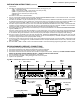
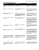
5. The MSC‑1 terminal blocks serve 5 distinct connection sectors (see Fig 4), they are:
1) TS‑1 ‑ temperature sensor,
2) MSA‑1 aerial sensors / MSG‑1 gutter sensors (one each per zone),
3) MSP‑1 in‑ground sensors (one each per zone),
4) Output to power contactors (one each per zone),
5) Power input.
Connection to each sector is described below.
6. The TS‑1 is connected to the left‑most terminal block, identified as TEMP. SENSOR. The MSC‑1 will not function if the TS‑1 wire colour
codes are not properly matched at the terminal block. See Fig.4
7. The MSA‑1 or the MSG‑1 may be connected to any one of the 3 terminal blocks, identified as A/G. SENS. The Zone number at the
terminal block correlates to a snow‑melting zone, ensure that the sensor is connected to the proper zone terminal. The MSC‑1 will
not function properly if the MSA‑1/MSG‑1 wire colour codes are not properly matched at the terminal block. See Fig.4
8. The MSP‑1 may be connected to any one of the 3 terminal blocks identified as PAV. SENS. The Zone number at the terminal block
correlates to a snow‑melting zone, ensure that the sensor is connected to the proper zone terminal. The MSC‑1 will not function
properly if the MSP‑1 wire colour codes are not properly matched at the terminal block. See Fig.4
9. The outputs to the power contactors may be connected to any one of the 3 terminal blocks in the –OUTPUT TO POWER CONTACTORS–
segment, ZONE#1, 2 or 3.
The Zone number at the terminal block correlates to a snow‑melting zone, ensure that the output being connected matches the
sensor inputs connected. The output wire must be connected with the polarity as noted, ensure voltage and amperages are suitable
for the contactor being used. The MSC‑1 will not function properly if the output connections are improperly made. See Fig.4
10. The power supply is connected to the right‑most terminal block, identified as POWER SUPPLY. The power supply wires must be
connected with the polarity as noted, ensure supply voltage is correct and noted ampacity is available. The MSC‑1 will not function
if the power supply connections are improperly made. See Fig.4
11. At this point a quick check on the power supply wiring can be made. Energize the supply circuit for the MSC‑1 Control Panel, and
turn on the MSC‑1 via the toggle switch, the LCD should illuminate at this point. Reattach the front access cover, connection of the
MSC‑1 is complete.
12. Each of the MSA‑1, MSG‑1 or MSP‑1 sensors connected to the MSC‑1 must be activated by programming the MSC‑1; to do so, follow
INSTALLATION INSTRUCTIONS
(continued)
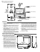
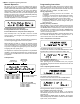
*As required by electrical codes
TS‑1 MSA‑1/MSG‑1 MSP‑1 Contactor Output
MSC‑1
Power
Input
MSA‑1 or MSG‑1
Sensor Wire
Conduit
*
Conduit
*
Contactor/
Connection
Box
Heating Mats/Cables
Outdoor
Connection
Box
240 Volt Power
Supply
L1
L2
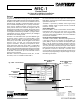
Fig.4 MSC‑1 Control Panel (access cover removed)
PRE‑PROGRAMMED (DEFAULT) CONNECTIONS
1. With the front access panel removed and wiring routed to the MSC‑1.
2. Connect the temperature sensor lead to the temperature sensor terminal block.
3. Connect the aerial or gutter sensor lead to the Zone 1 sensor terminal block.
4. Connect the control wire from the contactor coil to the Zone 1 output terminal block, 120VAC only. DO NOT CONNECT OUTPUT
DIRECT TO THE LOAD, THIS WILL DESTROY THE MSC‑1, RESULT IN RISK OF INJURY OR FIRE.
5. Connect 120VAC to the power supply terminal block, watch polarity.
6. Turn on the power to the MSC‑1 using the toggle switch on the front panel.
7. System is now operational.