
Specifications

166119 8/31/2006
67
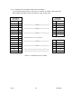
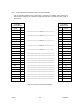
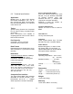
5.3.5 Channel Port X.21 Adapter Cable Connection Diagram
Use the following diagram when constructing or specifying an adapter cable between any
Nx8-DualMUX Channel port operating in EIA-530 mode and a standard X.21 cable, or DTE
device.
EIA-530 mode
25-pin Male
Sub-miniature D
X.21
15-pin Female
Sub-miniature D
Signal
Pin
Pin
Signal
TXD+
2
\
<><><><><><><><><> Twisted Pair <><><><><><><><>
/
2
Transmit+
TXD-
14
/
\
9
Transmit-
RXD+
3
\
<><><><><><><><><> Twisted Pair <><><><><><><><>
/
4
Receive+
RXD-
16
/
\
11
Receive-
RXC+
17
\
<><><><><><><><><> Twisted Pair <><><><><><><><>
/
6
Timing+
RXC-
9
/
\
13
Timing-
RTS+
4
\
<><><><><><><><><> Twisted Pair <><><><><><><><>
/
3
Control+
RTS-
19
/
\
10
Control-
CTS+
5
\
<><><><><><><><><> Twisted Pair <><><><><><><><>
/
5
Indication+
CTS-
13
/
\
12
Indication-
Ground
7
-
=============================================
-
8
Ground
Shield
1
-
=============================================
-
1
Shield
Table 22 – Channel Port to X.21 Adapter